


21
10
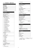
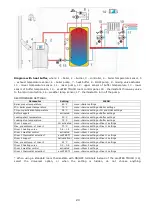
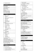
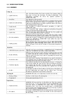
Technical data
Power supply
230V~, 50Hz
Current consumption by
the regulator
0,2 A
Max. rated current
6 (6) A
IP rating of the regulator
IP20
Ambient temperature
T50
Ambient temperature
0...50
C
Storage temperature
0...65
C
Relative humidity
5 - 85% without
steam condensation
Temperature measurement
range of sensors CT4
0...100
C
Temperature measurement
range of sensors CT6-P
-35...40
C
Accuracy of temperature
measurement using
sensors CT4 and CT6-P
2
C
Connectors
Screw terminals at
supply voltage side -
2.5mm
2
Screw terminals at
control voltage side -
1.5mm
2
Graphical display with
touch panel
Display 480x272 pix.
Overall dimensions
340x225x60mm
Total weight
1,6 kg
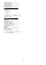
Standards
PN-EN 60730-2-9
PN-EN 60730-1
Software class
A
Pollution degree
2nd pollution degree
11
Storage and transport conditions
The controller cannot be exposed to
immediate effects of atmospheric conditions
i.e. rain or sunrays. Temperature of storage
and transport should be within scope
-15…+65°C.
During transport the controller cannot be
exposed to vibrations bigger than typical for
transport of boilers as well as direct pressure
upon the clamp cover in order to protect the
STB capillary, which is situated inside the
clamp box for the controller version equipped
with STB device.
12
REGULATOR INSTALLATION
12.1
Environmental conditions
Due to fire risk it is forbidden to use the
controller in proximity of explosive gases or
dust. Moreover the controller cannot be used
in conditions of water steam condensation or
be exposed to effects of water.
12.2
Mounting requirements
Regulator should be installed by qualified and
authorized technician with observance of
applicable standards and regulations. The
manufacturer disclaims any liability for
damage caused by non-observance of
instructions specified in this manual. The
regulator is intended to build into other
equipment, and may not be used as a
stand-alone device.
Ambient temperature and temperature of
mounting base should be within the range of
0…+50˚C. The regulator is composed of two
modules: a control panel and an operating
unit, connected with electric wire.
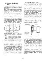
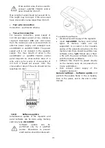
12.3
Module installation
The regulator casing does not provide dust
and water immunity. In order to provide the
protection from these factors the regulator
should be enclosed with a proper casing.
The regulator is to be enclosed – which
means the regulator should be screwed on to
the flat horizontal or vertical surface (e.g.
boiler housing, room wall). To screw on the
regulator use mounting holes and proper
screws. Location and spacing of mounting
holes are shown in the picture below. The
regulator must not be used as a free-
standing device.
After installation make sure that the device is
properly mounted and it is impossible to
detach it from the mounting surface.
Summary of Contents for ecoMAX860P TOUCH
Page 2: ......
Page 6: ...6...
Page 7: ...INSTRUCTION MANUAL ecoMAX 860P TOUCH...
Page 17: ...INSTALLATION AND SERVICE SETTINGS ecoMAX 860P TOUCH...
Page 43: ......