


13
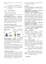
Settings for mixer with weather sensor
without
room
thermostat
ecoSTER
TOUCH
Set parameter Mixer weather control to On.
Select weather curve. Using parameter
Curve
translation,
set
preset
room
temperature following the formula:
Preset room temperature = 20°C + heating
curve translation.
In this setup, it is possible to connect a room
thermostat which will equalize the inaccuracy
of selecting heating curve, if the selected
heating curve value is too high. In such case,
it is necessary to set the value of preset
mixer temperature decrease by thermostat,
e.g. at 2°C. After opening of the thermostat
contacts,
the
preset
mixer
circuit
temperature will be decreased, which, if
proper decrease value is selected, will stop
growth of temperature in the heated room.
Settings for mixer with weather sensor
and with room thermostat
Set parameter Mixer weather control to On.
Select weather curve. The room panel
automatically translates the heating curve,
depending on the preset room temperature.
The regulator relates the setting to 20°C,
e.g. for preset room temperature = 22°C,
the regulator will translate the heating curve
by 2°C, for preset room temperature = 18°C,
the regulator will translate the heating curve
by -2°C.
In some cases it may be necessary
to fine-tune the heating curve translation.
In this setup, the ecoSTER TOUCH room
thermostat can:
- decrease the heating cycle temperature by
a constant value when the preset room
temperature is reached. Analogously, as
specified in the previous point (not
recommended), or
- automatically, continuously correct the
heating cycle temperature.
It is not recommended to use both options at
the same time.
Automatic correction of room temperature is
carried out in accordance with the following
formula:
Correction = (Preset room temperature -
measured room temperature) x room
temperature coefficient /10
Example:
Preset temperature in the heated room (set
at ecoSTER TOUCH) = 22°C. Temperature
measured in the room (by ecoSTER TOUCH)
= 20°C. Room temp. factor. = 15.
Preset mixer temperature will be increased
by (22°C - 20°C) x 15/10 = 3°C.
It is necessary to find appropriate value of
the Room temp. factor. The higher the
coefficient, the greater the correction of
preset boiler temperature. If the setting is
“0”, the preset mixer temperature is not
corrected. Note: setting a value of the room
temperature coefficient too high may cause
cyclical fluctuations of the room temperature!
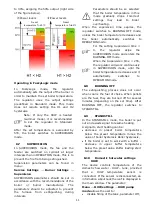
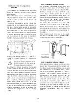
8.17
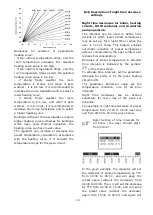
Weather controlled
Depending on the temperature measured
outside the building, both preset boiler
temperature and temperatures of mixer
circuits can be controlled automatically. If
proper heating curve is selected, the
temperature of the circuits is calculated
automatically, depending on the outdoor
temperature. Thus, if the selected heating
curve is appropriate for the given building,
the room temperature stays more or less the
same, regardless of the temperature outside.
Note: during trial and error selection of
appropriate heating curve, it is necessary to
exclude influence of the room thermostat on
regulator operation (regardless of whether
the room thermostat is connected or not), by
setting the parameter:
Mixer 1 settings
→
Mixer room therm. =
0.
If a room panel ecoSTER TOUCH is
connected, it is also necessary to set the
parameter Room temperature factor = 0.
Guidelines for proper setting of the heating
curve:
floor heating
0,2 -0,6
radiator heating
1,0 - 1,6
boiler
1,8 - 4
Summary of Contents for ecoMAX860P TOUCH
Page 2: ......
Page 6: ...6...
Page 7: ...INSTRUCTION MANUAL ecoMAX 860P TOUCH...
Page 17: ...INSTALLATION AND SERVICE SETTINGS ecoMAX 860P TOUCH...
Page 43: ......