


22
English
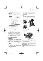
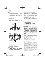
3. Cutting
Operation
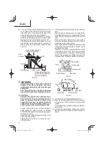
(1) As shown in Fig. 24 the width of the saw blade is the
width of the cut. Therefore, slide the workpiece to
the right (viewed from the operator’s position) when
length
ⓑ
is desired, or to the left when length
ⓐ
is
desired.
Turn the LED light, project the shadow of the blade
onto the workpiece, align the left side or right side of
shadow of the blade with the ink line on the workpiece.
(2) Once the saw blade reaches maximum speed,
push the handle down carefully until the saw blade
approaches the workpiece.
(3) Once the saw blade contacts the workpiece, push the
handle down gradually to cut into the workpiece.
(4) After cutting the workpiece to the desired depth,
turn the power tool OFF and let the saw blade stop
completely before raising the handle from the
workpiece to return it to the full retract position.
Adjusting line
Marking
(pre-marked)
Marking
(pre-marked)
(Front view)
ⓑ
ⓑ
ⓑ
ⓐ
ⓐ
ⓐ
Fig. 24
CAUTION
●
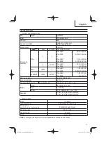
For maximum dimensions for cutting, refer to
“SPECIFICATIONS” table on page 13.
●
Increased pressure on the handle will not
increase the cutting speed.
On the contrary, too much pressure may result in
overload of the motor and/or decreased cutting
e
ffi
ciency.
WARNING
To avoid injury, after completing a cut and
releasing the trigger switch, allow the blade to
stop before raising the saw head.
WARNING
Never lock the Lock-o
ff
button in depressed
position.
Pulling back the switch would then cause the tool
to suddenly start operating, which could result in
injury.
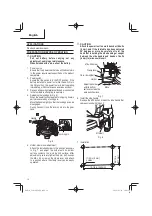
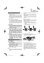
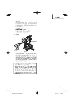
2. Using the Vise Assembly (Standard accessory)
(1) The vise assembly can be mounted on either left side
of the fence or right side of the fence by loosening the
6 mm wing bolt (A).
(2) The screw holder can be raised or lowered according
to the height of the workpiece by loosening the 6 mm
wing bolt (B). After the adjustment,
fi
rmly tighten the
6 mm wing bolt (B) and
fi
x the screw holder.
(3) Turn the upper knob and securely
fi
x the workpiece in
position (Fig. 23).
Screw holder
Knob
Work piece
Vise plate
6 mm Wing bolt (B)
Fence
6 mm Wing bolt (A)
Vise shaft
Fig. 23
WARNING
Always
fi
rmly clamp or vise to secure the
workpiece to the fence; otherwise the workpiece
might be thrust from the table and cause bodily
harm.
CAUTION
Always
con
fi
rm that the motor head does not contact
the vise assembly when it is lowered for cutting. If
there is any danger that it may do so, move the vise
assembly to a position where it will not contact the
saw blade.
00Book̲C1810DFA̲NA.indb 22
00Book̲C1810DFA̲NA.indb 22
2022/02/22 14:08:17
2022/02/22 14:08:17