


19
English
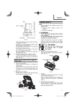
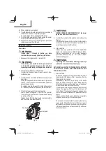
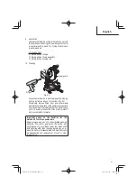
WARNING
Please be aware of the reaction of the Motor
Head (Fig. 2) when the brake is activated.
Braking causes the Motor Head to jerk downward
and the user should be prepared for this
reaction, especially when the trigger switch is
released before the blade is completely down.
Failure to be familiar with, and prepared for, the
operational characteristics of the tool may cause
serious injury.
8. Trial
Run
After
con
fi
rming that no one is standing behind,
the power tool start and con
fi
rm that no operating
abnormalities exist before attempting a cutting
operation.
9. Inspect the rotating stability of the saw blade.
For precise cutting, rotate the saw blade and check for
de
fl
ection to con
fi
rm that the blade is not noticeably
unstable; otherwise vibrations might occur and cause
an accident.
BEFORE CUTTING
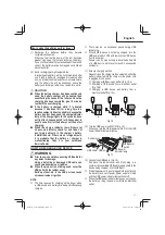
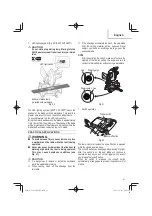
1. Install the sub fence
In the case of direct angle cutting and angle cutting,
use the sub fence. The sub fence can be installed on
the left side of the guide fence. Place the attached
plate in the position as shown in Fig. 15-a, insert the
tip in the groove of fence and simultaneously, insert
fl
athead screw M6 into fence, sub fence, and plate,
then tighten nylon nut M6 with the 10 mm box wrench
until the sub fence can smoothly rotate. Then, you can
realize stable cutting of the material with a wide back
face.
Sub fence
M6 Flat screw
Plate
M6 Nylon nut
Fence
Fig. 15-a
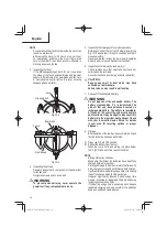
WARNING
In the case of left bevel cutting, rotate the sub
fence. Supposing it is not able to rotate it, It
will contact the blade or some part of the tool,
causing in serious injury to operator.
Sub fence
Fence
Fig. 15-b
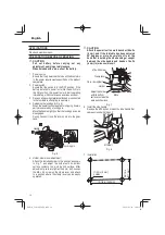
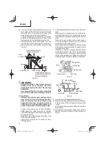
2. Oblique
angle
Before the power tool is shipped from the factory, it
is adjusted for 0°, left 45° bevel cutting angle with the
8 mm bolt (A) and the 8 mm bolt (B).
When changing the adjustment, change the height of
the 8 mm bolt (A) or the 8 mm bolt (B) by turning them.
(Fig. 16-a, Fig. 16-b)
8 mm Bolt (A)
(Stopper for 0°)
Indicator (B)
(For bevel scale)
Fig. 16-a
00Book̲C1810DFA̲NA.indb 19
00Book̲C1810DFA̲NA.indb 19
2022/02/22 14:08:14
2022/02/22 14:08:14