


•
The maximum allowable distance between any two modules is 40.2 m (132 ft) (36.6 m [120 ft] trunk plus 1.8 m [6.0 ft] on
each end).
•
The CAN bus will support a maximum of 20 devices.
On dual engine applications, instrument harness part number 84‑892323Txx (or equivalent for triples and quads) allows
activation of all gauges from any key switch.
When installing a blue CAN data or System Tach/Speed harness, the end of the harness with multiple connectors must be
connected to the SC1000 gauge. The System Link signals come from the SC1000 gauge. If the harness is reversed, there is no
path for the System Link signals to transfer from the SC1000 gauge to the System Link gauges.
CAN Bus Overview
The wires required for three controller area network (CAN) buses can be found within the 14‑pin harness that connects the
engine to the helm. These buses carry communications between the various controllers used by the engines and helms. Each
CAN bus consists of a twisted pair of wires—twisting the pair helps prevent electrical interference. If either wire develops an
open or short, that CAN bus will stop communicating.
Only one CAN is used on the engines covered by this manual. This CAN is known as CAN P. The CAN P (propulsion) circuit
(blue and white wires) connects together the engine modules, helm modules, and SmartCraft gauges and displays. Its primary
purpose is to provide a path for data (such as temperatures, pressures, depth, boat speed, tank levels, and engine speed) to
the SmartCraft gauges and displays. It is also used by diagnostic tools, such as CDS G3. There is one CAN P bus per boat,
regardless of the number of engines or helms.
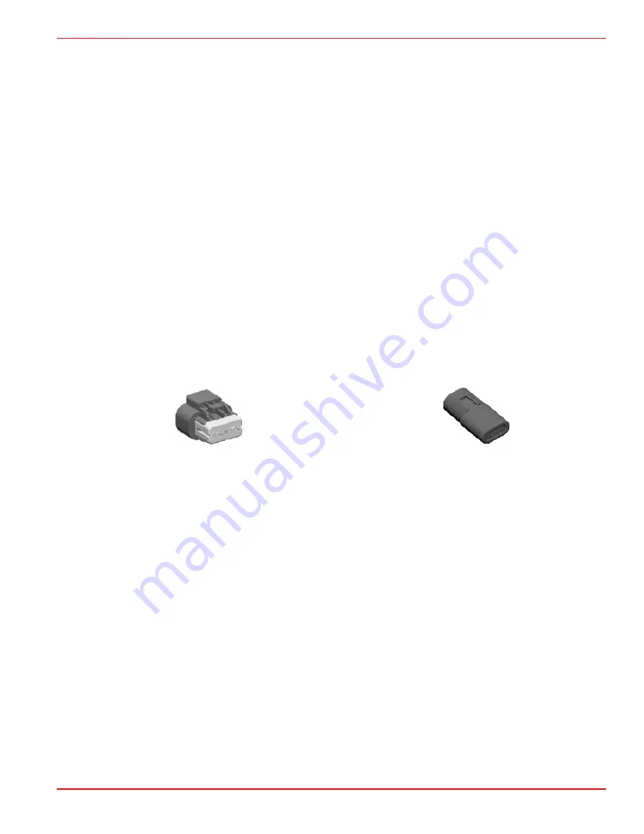
Termination Resistors
Termination resistors are CAN line signal conditioners. The resistor places a known load on the CAN line to ensure proper
system communication. All CAN bus termination resistors are 120 ohms. Each CAN bus has two termination resistors installed,
one at each of the furthest ends of the bus' running length. With all modules and gauges disconnected from the bus, the
resistance between the two data communication wires of the CAN bus should be approximately 60 ohms. Incorrect CAN bus
termination, usually caused by too few or too many installed termination resistors, will result in communication errors or
complete failure of that CAN bus.
17168
Yellow 10-pin termination resistor
29610
Blue 2-pin termination resistor
Boat Harnesses and Installation Connections
Engine Harness and Accessory Power Supply
If the engine harness is used to supply power for boat accessories (lights, blower, pumps, stereo, or any other electrical device
using the engine wiring harness for power), the maximum accessory power available on the 14‑pin wiring harness is 15 amps.
Relay kits are available to provide additional accessory power at the helm. This maximum is fuse‑protected and must be
observed. If the fuse opens, the engine will stop and will not restart until the fuse is corrected.
Boat Wiring
NOTE: Twin engines are treated as two single engines in the same boat. No twin engine disconnect is required.
Instrumentation and Controls
90-8M0099748 eng DECEMBER 2015
© 2016 Mercury Marine
Page 4D-7
Summary of Contents for MERCRUISER
Page 2: ......
Page 6: ...90 8M0099748 eng DECEMBER 2015 2016 Mercury Marine Page iv...
Page 12: ...General Information Notes Page 1A 6 2016 Mercury Marine 90 8M0099748 eng DECEMBER 2015...
Page 70: ...Maintenance Notes Page 1C 54 2016 Mercury Marine 90 8M0099748 eng DECEMBER 2015...
Page 96: ...Troubleshooting Notes Page 1D 26 2016 Mercury Marine 90 8M0099748 eng DECEMBER 2015...
Page 156: ...Installation Notes Page 2B 52 2016 Mercury Marine 90 8M0099748 eng DECEMBER 2015...
Page 202: ...Engine Disassembly Notes Page 3A 46 2016 Mercury Marine 90 8M0099748 eng DECEMBER 2015...
Page 286: ...Engine Troubleshooting Notes Page 3C 14 2016 Mercury Marine 90 8M0099748 eng DECEMBER 2015...
Page 314: ...Waste Spark System Notes Page 4B 8 2016 Mercury Marine 90 8M0099748 eng DECEMBER 2015...
Page 330: ...Charging System Notes Page 4C 16 2016 Mercury Marine 90 8M0099748 eng DECEMBER 2015...
Page 404: ...MPI ECT Fuel System Notes Page 5A 34 2016 Mercury Marine 90 8M0099748 eng DECEMBER 2015...
Page 424: ...All Models Notes Page 6A 20 2016 Mercury Marine 90 8M0099748 eng DECEMBER 2015...
Page 448: ...Models with Closed Cooling Notes Page 6C 20 2016 Mercury Marine 90 8M0099748 eng DECEMBER 2015...
Page 462: ...Water Flow Diagrams Notes Page 6D 14 2016 Mercury Marine 90 8M0099748 eng DECEMBER 2015...
Page 474: ...Important Information Notes Page 7A 12 2016 Mercury Marine 90 8M0099748 eng DECEMBER 2015...
Page 477: ...Manifolds and Elbows Notes 90 8M0099748 eng DECEMBER 2015 2016 Mercury Marine Page 7B 3...
Page 538: ...Compact Hydraulic Steering Notes Page 8B 12 2016 Mercury Marine 90 8M0099748 eng DECEMBER 2015...
Page 558: ...Notes Color Diagrams Page 10A 2 2016 Mercury Marine 90 8M0099748 eng DECEMBER 2015...
Page 559: ...Notes Color Diagrams 90 8M0099748 eng DECEMBER 2015 2016 Mercury Marine Page 10A 3...
Page 565: ......