


Powerhead
90-8M0050731 MAY 2011
Page 4A-41
2. A tool can be made for cleaning the inner diameter of the tapered ring grooves. The tool can be made from a broken tapered
piston ring with the side taper removed to enable the inside edge of the ring to reach the inner diameter of the groove. Carefully
scrape carbon from the inner diameter of the ring grooves. Care must be taken not to damage the grooves by scratching the
side surfaces of the grooves.
a -
Ring grooves
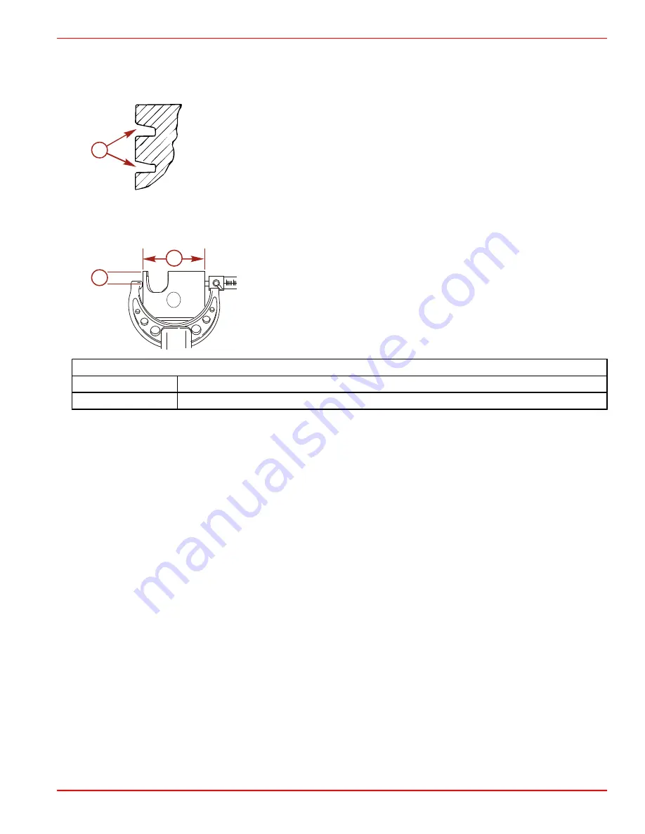
Measuring Piston
The piston has a barrel profile shape and is not a true diameter.
Measure the piston at a point 24 mm (0.945 in.) from the bottom of the piston skirt, 90° to the wrist pin opening.
a -
24 mm (0.945 in.)
b -
Piston diameter
Piston diameter
Standard
88.7095 ± 0.0127 mm (3.4925 ± 0.0005 in.)
Oversize
89.0905 ± 0.0127 mm (3.5075 ± 0.0005 in.)
Cylinder Heads and Exhaust Divider Plate
1. Inspect the internal surface of the cylinder heads for possible damage as a result of piston or foreign material striking the
cylinder heads.
IMPORTANT: Cylinder head warpage must not exceed 0.025 mm (0.001 in.) over the entire length of the cylinder head. If
the warpage exceeds 0.025 mm (0.001 in.) in the narrow portion of the cylinder head, the cylinder head must be replaced.
The cylinder head must not be resurfaced, as the O‑ring groove depth in the head will be reduced, which will result in cylinder
leakage.
2. Replace the cylinder head as necessary.
3. Thoroughly clean the gasket surfaces of the exhaust divider plate.
4. Inspect the exhaust divider plate for deep grooves, cracks, or distortion that may cause leakage. Replace the part as
necessary.
Crankshaft
1. Inspect the splines on the crankshaft end of the driveshaft for wear. Replace the crankshaft if necessary.
2. Check the crankshaft for runout. Maximum runout is 0.152 mm (0.006 in.). Replace the crankshaft if necessary.
3. Inspect the crankshaft oil seal surfaces. The sealing surfaces must not be grooved, pitted, or scratched. Replace the crankshaft
if necessary.
4. Check all crankshaft bearing surfaces for rust, water marks, chatter marks, uneven wear, or overheating.
a
8652
b
a
33506
Summary of Contents for 200 OptiMax Jet Drive
Page 5: ...Page iv ...
Page 30: ...General Information Notes 90 8M0050731 MAY 2011 Page 1C 5 ...
Page 43: ...General Information Notes Page 1C 18 90 8M0050731 MAY 2011 ...
Page 84: ...Ignition Notes 90 8M0050731 MAY 2011 Page 2A 3 ...
Page 89: ...Ignition Page 2A 8 90 8M0050731 MAY 2011 Electrical Plate Engine Harness 44731 1 2 3 4 5 6 ...
Page 147: ...Charging and Starting System Notes Page 2B 36 90 8M0050731 MAY 2011 ...
Page 153: ...Timing Synchronizing and Adjusting Notes Page 2C 6 90 8M0050731 MAY 2011 ...
Page 156: ...Fuel Pump Notes 90 8M0050731 MAY 2011 Page 3A 3 ...
Page 245: ...Direct Fuel Injection Notes Page 3B 82 90 8M0050731 MAY 2011 ...
Page 248: ...Oil Injection Notes 90 8M0050731 MAY 2011 Page 3C 3 ...
Page 261: ...Oil Injection Notes Page 3C 16 90 8M0050731 MAY 2011 ...
Page 277: ...Powerhead Page 4A 12 90 8M0050731 MAY 2011 Cylinder Head 14 44903 1 2 3 3 4 5 6 7 8 9 10 ...
Page 326: ...Powerhead 90 8M0050731 MAY 2011 Page 4A 61 Starboard Side Oil Hose Routing 45579 ...
Page 327: ...Powerhead Page 4A 62 90 8M0050731 MAY 2011 Port Side Oil Hose Routing 45580 ...
Page 339: ...Powerhead Notes Page 4A 74 90 8M0050731 MAY 2011 ...
Page 346: ...Cooling Notes 90 8M0050731 MAY 2011 Page 4B 7 ...
Page 349: ...Cooling Notes Page 4B 10 90 8M0050731 MAY 2011 ...