background image

MCR  

P

ROSMOKE 

FS 

 
O

PERATION AND 

M

AINTENANCE 

M

ANUAL


Page 8 of 20 

c.  Unscrew  the  four  screws  securing  the  roller  support  located  on  the  opposite 

side of the motor. 

d.  Pull out the shaft end with a plug (opposite the motor). 
e.  Remove the roller from the casing. 

3.  Make mounting holes in the casing. 
4.  Mount  the  curtain  housing  using  steel fasteners  adequate for  the  substrate  material 

and  for  the  position  of  the  mounting  surface  (ceiling/wall):  fasteners  with  a  joining 
element of at least Ø10 in diameter are recommended, e.g. M10 (such as HK8 HILTI 
anchors). Note the length of the fastener  inside the casing as it cannot damage the 
fabric. 

5.  When the casing has been installed, put the roller with fabric inside. Follow the above 

steps in reverse order. Make sure that the position of the roller is the same as before 
removing it.  

6.  Secure the roller by locking pins at both ends. 
7.  Install the side guides, if ordered, using steel fasteners. 

Connect  the  free  terminals  of  MECU  XL 

(fig.  12)

  to  the  control  device,  i.e.  the  mcr 

9705 or mcr 0204 control unit, and to the 230 V power supply. Observe polarity (+ to 
+, - to -). The mcr 9507 control unit should be set to the door control mode (see the 
OMM of the smoke vent control unit) or the mcr 0204 control unit should be set to the 
curtain control mode. 

8.  Make sure that there are no obstacles under the curtain and check if the curtain rolls 

out to the desired height and rolls up properly. Adjust the length of the fabric feed, if 
required (see: Limit switch adjustment 

– page 9). 

9.  Having checked and adjusted it, close the access cover. 
10. Check the system operation by triggering the alarm from all available sources. 


Curtains with a bottom bar masking element: 

Masking  elements  are  supplied  separately.  They  are  suitable  for  installation  at  the 
already mounted and adjusted curtains. 

1.  Before  installing  the  masking  element,  attach  the  bracket  to  a  spring  which  is 

attached  to  the  masking  element  by  default.  The  installation  takes  place  on  site  by 
putting the spring in the prepared slot in the bracket. 

2.  The  masking  element  with  the  bottom  bar  bracket  is  to  be  attached  using  4.8  x13 

buttonhead self-drilling screws. 

3.  Restrictions on the use of the masking element with holders 

(fig. 4, 5).


Multi-modular  curtains  should  be  installed  following  the  order  of  modules  (first  the 

edge module, then the central one and then the edge one again) and design sizes of material 
overlaps in the individual modules. 

For  a  group  of  curtains  with  a  common  bottom  bar,  all  curtain  modules  should  be 

powered  by  the  same  source,  i.e.  by  a  single mcr  9705  or  mcr  0204  control  unit.  Electrical 
connections should be as specified in the OMM of the control units. 

The  installation  of  a  single  bottom  bar  for  a  group  of  curtains  and/or  the  masking 

element should be as specified in a separate manual. 


NOTE: 

In the case of curtains longer than 4 m, there is foam padding inside the casing. Make 
sure to remove it before powering the curtains. 
 Failure to remove the foam padding 

may result in damage to the drive or fabric.


Summary of Contents for mcr Prosmoke FS

Page 1: ...Gdańsk ver 3 1 0 2017 11 24 ul Grzegorza z Sanoka 2 80 408 Gdańsk phone 48 58 341 42 45 phone fax 48 58 341 39 85 OPERATION AND MAINTENANCE MANUAL OMM Automatic rolling curtain mcr PROSMOKE FS ...

Page 2: ...nts mcr PROLIGHT system skylights and smoke exhaust vents integrated with continuous rooflights mcr 9705 and mcr 0204 smoke exhaust control units and others mcr PROSMOKE FS rolling curtains are used to define smoke zone in the space under the ceiling in smoke and heat gravitational exhaust systems Fire smoke is collected in the smoke containers and then is removed by smoke exhaust vents e g mcr PR...

Page 3: ...t and rolling up and minimising the risk of bending and lifting the fabric when affected by the pressure of fire gases The bottom bar may be optionally equipped with a masking element fig 5 The masking element is an 80 mm wide aluminium profile painted to order in any RAL colour The smoke tight fabric used in mcr PROSMOKE FS curtains is not trimmed at the edges Slight edge fraying is natural and d...

Page 4: ...ements projecting beyond the mcr PROSMOKE FS curtain casing outline TYPE K CASING TYPE C CASING Fig 2 Curtain casing types K C Mounting surface Mounting surface NOTE When planning the curtain installation the presence of any elements projecting beyond the casing outline should be taken into account ...

Page 5: ...g 3 Curtain casing types L K T Note ensure straightness and flatness 5 mm 5000 mm of the drop ceiling surface around the gap Fig 4 Recommended position of casings relative to the ceiling Gap width Mounting surface Mounting surface approx 85 105 approx 15 35 optimum height recommended compression ...

Page 6: ...ol unit to the curtain is interrupted for one of the following reasons alarm signal disconnection or power shortage including burning out in case of fire of the circuit connecting the mcr 9705 or mcr 0204 control unit with the MECU XL motor control system failure of 230 V power supply to the mcr 9705 or mcr 0204 and discharged control unit batteries the brake is released and the curtain fabric dro...

Page 7: ...uld be fastened together as shown in fig 9 by means of self drilling screws or rivets not longer than 20 mm so that uncontrolled movements of casings relative to each other are eliminated Curtain installation should be carried out as follows Curtains with brackets 1 Mount M10 or M12 threaded rods of suitable length in the structural component to match the arrangement of brackets fig 7 To mount the...

Page 8: ...roperly Adjust the length of the fabric feed if required see Limit switch adjustment page 9 9 Having checked and adjusted it close the access cover 10 Check the system operation by triggering the alarm from all available sources Curtains with a bottom bar masking element Masking elements are supplied separately They are suitable for installation at the already mounted and adjusted curtains 1 Befor...

Page 9: ...ly 4 The maximum power of a 230 V motor in a single module is 270 W Limit switch adjustment The mcr PROSMOKE FS only has the upper position limit switch The lower position limit switch is blanked off photo 1 the curtain drops until it is fully rolled out 1 The limit switch is marked with up down arrows which correspond to the direction of the motor rotation symbols indicate the change in range 2 T...

Page 10: ...MCR PROSMOKE FS OPERATION AND MAINTENANCE MANUAL Page 10 of 20 Photo 1 Curtain motor limit switches Wide suspension bracket TYPE A Narrow suspension bracket TYPE B Blanking plug ...

Page 11: ...FS OPERATION AND MAINTENANCE MANUAL Page 11 of 20 Flat suspension bracket TYPE C installation directly to the ceiling only Fig 7 Suspension bracket types Fig 8 Installation of a curtain without a suspension bracket ...

Page 12: ...0 Schematic diagram of the curtain connections with a common bottom bar CABLES Regular cable 2 x 1 5 mm 2 5 mm NOTE In the case of multi modular curtains cables of the same length must be used to ensure the same supply voltage drop Single curtain Multi modular curtain Smoke detector Manual venting button Control panel MCR 9705 MCR 0204 ...

Page 13: ...ortant To roll the curtain down to the intermediate position remove the jumper H2 then temporarily remove the jumper H1 until the curtain descends to the desired position The installation of the H2 jumper causes the curtain to roll up Fig 11 MECU XL service functions jumpers 1 H1 jumper removal releases the brake 24V curtain descent H2 Control panel 24V 230V FS H1 MECU XL ...

Page 14: ...op ceiling proper gaps and tolerances should be ensured fig 4 5 matching a given curtain width 3 Do not disconnect the MECU motor control system from the motor Disconnection or damage to the connection between the MECU system and the motor may result in the rolling out of the fabric If disconnection is necessary the curtain should be protected against rolling out Fig 13 Typical gap sizes in the tr...

Page 15: ...fabrics overlapping Fig 15 Typical gap sizes in the transverse direction in the case of butt arrangement of curtain modules with type K C and L casings and with fabrics overlapping Fig 16 Typical gap sizes in the transverse direction in the case of butt arrangement of curtain modules with type K C and L casings and without fabrics overlapping typically 250 200 typically 250 200 ...

Page 16: ...g a common bottom bar type F casings arranged vertically and horizontally Fig 18 Typical gap sizes in the transverse direction in the case of butt arrangement of curtains type K C and L casings Fig 19 Overlapping bottom bar no connection of curtains by means of a common bottom bar where L1 fabric lap L2 bottom bar lap ...

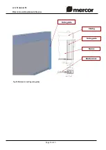
Page 17: ...ND MAINTENANCE MANUAL Page 17 of 20 Fig 20 Lengths of gaps in the longitudinal direction of mcr PROSMOKE FS curtains Fig 21 Curtain ready to be fitted with side guides Curtain fabric Bottom bar for the guide where S module width ...

Page 18: ...MCR PROSMOKE FS OPERATION AND MAINTENANCE MANUAL Page 18 of 20 Fig 22 Method of installing side guides Side guide Casing Side guide Fabric Bottom bar ...

Page 19: ...n will be considered Hurricane is defined as wind blowing at the speed of at least 17 5 m s damages are deemed to have been caused by hurricane if the effects of hurricane have been found in the immediate neighborhood damages due to failure to immediately report the defect discovered worsened quality of coating due to the natural ageing process fading oxidation defects due to using abrasive or agg...

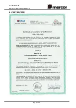
Page 20: ...MCR PROSMOKE FS OPERATION AND MAINTENANCE MANUAL Page 20 of 20 8 CERTIFICATE ...

Reviews: