mcr-PROLIGHT
VENTS
,
TYPE
:
DVP,
DVPS
O
PERATION AND MAINTENANCE MANUAL
Page 6 of 30
5. DEVICE INSTALLATION
The device must be installed in observance of all the applicable SHE principles, particularly
those related with working at height, using adequate personal protective equipment.
The vents must rest on the roof's structural elements such as: purlin, trimmers, structural sheet,
reinforced concrete plinth. Any elements causing collision with the vent leaf at full opening
range should be removed.
The vents may be installed on roofs of steel, concrete or wooden structure. The vent base has a
protrusion (shelf) in its lower part, allowing to rest and fix the vent to the supporting structure.
Fixture elements should be selected depending on the supporting structure's making, according
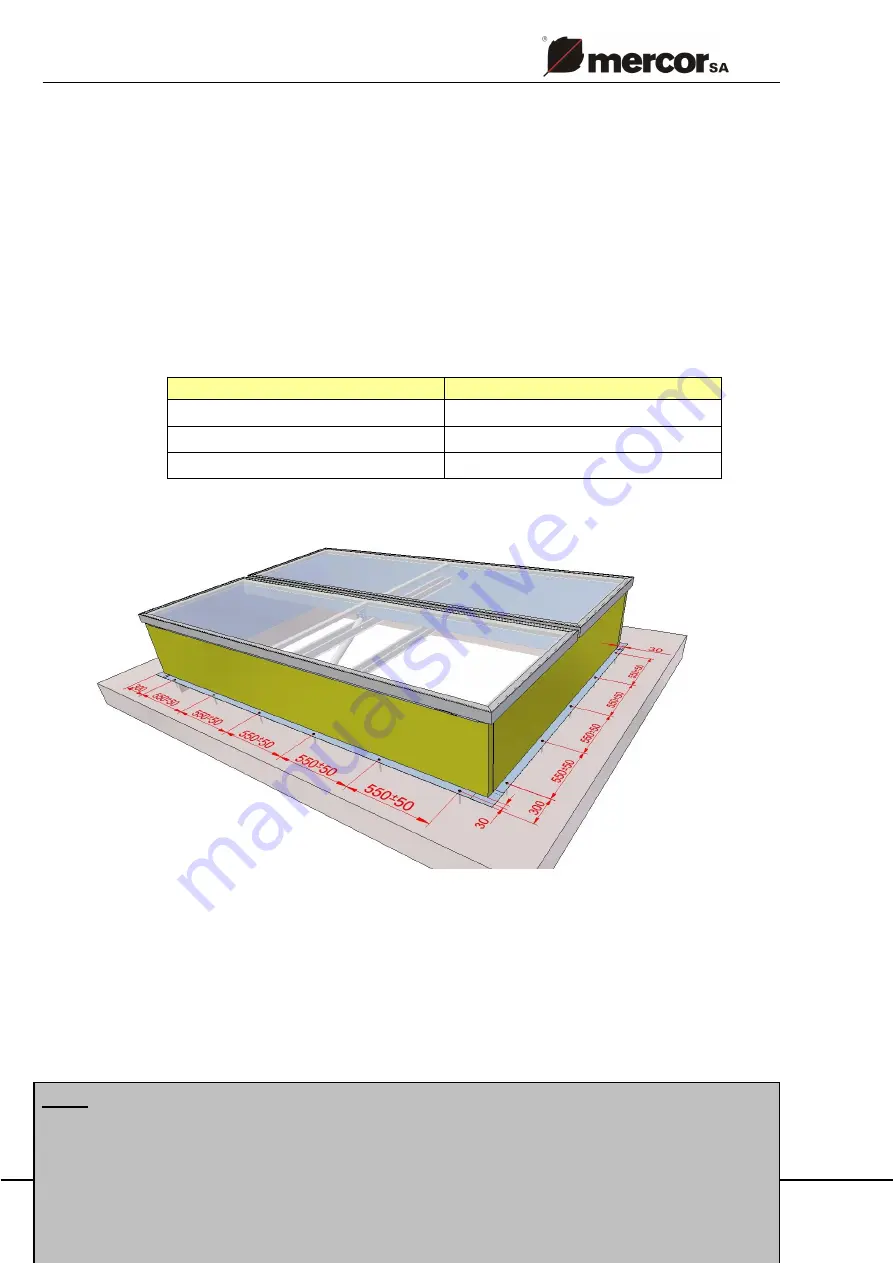
to the below table. Fixtures should be installed at 50
÷
60 cm spacing.
supporting structure type
minimum fixture diameter
steel
min.
Ø
4.8 mm
concrete
min. Ø6 mm
wood
min. Ø6 mm
Fig. 4 Method of mcr-PROLIGHT DVP positioning on the roof - fixtures spacing
The vent bases are ready for flashing works with roofing paper, PVC membrane or steel sheet.
The vent base, in its upper part, features a galvanized steel sheet strip at its full circumference,
which is used for fixing flashings/coverings using screws. For roofs covered with roof
membrane, an optional PVC-coated sheet strip may be used to facilitate installation.
NOTE
1. If roofing paper is to be welded to the above mentioned sheet strip, IT IS
ABSOLUTELY REQUIRED to use a cover for protecting the vent glazing and
spacer sleeves from the effect of fire/hot air.


