Operating Instructions - CPC3050
15
High-Speed Pressure Controller
CPC3050
3.4 Display
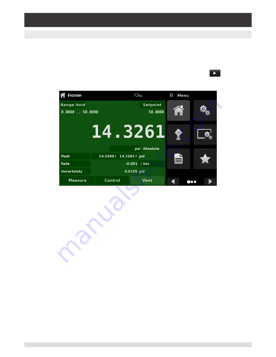
The display is made up of two sections. In the main screen (“Home Application”), the left three fourths
shows the operating screen with the control channel. The control channel displays the active pressure
reading, units, mode (absolute or gauge), active range of the internal transducer, pressure control set-
point, a bar graph (if enabled), tare button (if enabled) and any auxiliary displays that have been chosen.
The right one fourth of the screen has Application Icons (“Apps”) for setting general instrument settings,
control settings, display settings, program settings, favorites plus a “Next Page” button [
] that, when
pressed, shows a second and third page of icons for information, troubleshooting, remote communica-
tion, step setting, leak test and service applications.
Buttons, Labels and Windows:
The CPC3050 touch screen has many buttons with relevant graphic
icons or text which, when pressed, will open a related window where changes can be made or informa-
tion viewed. Some of these buttons will toggle from one state to another, others present choices or dis-
play a numerical data entry screen. Text or icons that are displayed, but do not respond to being touched,
are called labels or windows. Operators will quickly become accustomed to the particular characteristics
of the frequently used buttons.
Main Screen:
The main screen or “Home Application”, appears after power-up. This screen contains the
operating screen and Settings application screen. It will remain as configured after a power cycle.
Operating screen:
The operating screen (left 3/4 of the screen) contains information relevant to the
measurement. Up to three auxiliary displays can be shown simultaneously along with the current pres-
sure value. The operating mode of the instrument can be selected and changed in this screen between
“Measure”, “Control” and “Vent”.


