User guide
Wireless remote control M-WRG-FBH
- 34 -
Meltem Wärmerückgewinnung GmbH & Co. KG
Am Hartholz 4 · D-82239 Alling
[email protected] · www.meltem.com
VENTILATION THE RIGHT WAY
V E N T I L A T I O N & H E A T R E C O V E R Y
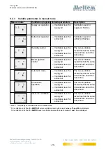
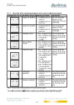
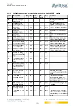
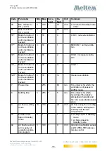
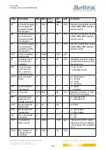
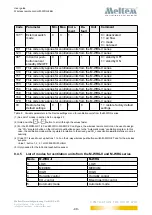
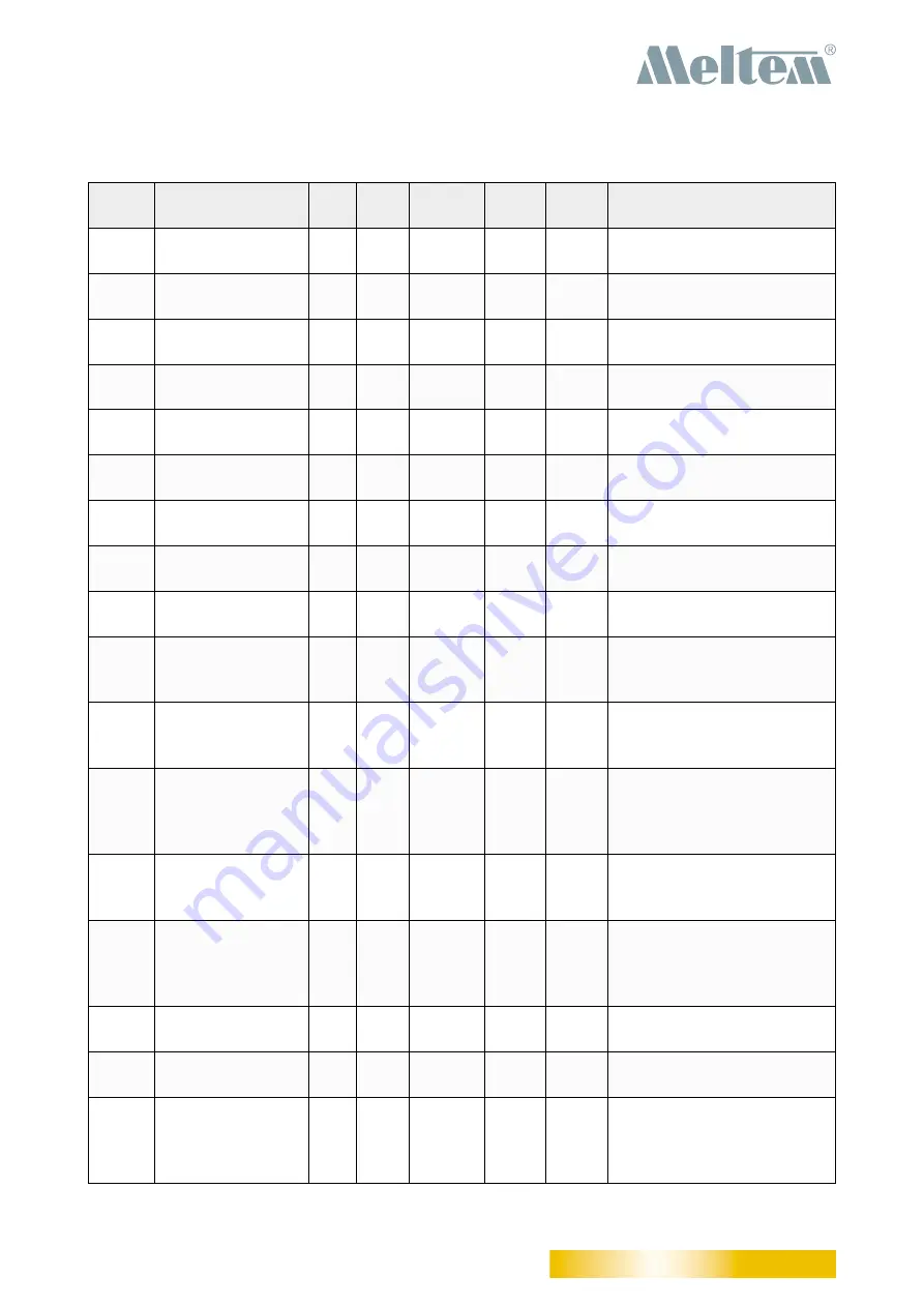
9.4.3 Variable parameters for ventilation units from the M-WRG-II series
Code Parameter
Min. Max. Incre-
ment
De-
fault
Unit
Comment
84
Fan motors oper-
ating hours
Running time of the fan
motors
83
Ventilation unit
operating hours
Unit switched on (also
applies to standby mode)
13
Air flow in
LOW mode
0
100
1
10
m
3
/h
LOW = reduced ventilation
14
Air flow in
MEDIUM mode
0
100
1
30
m
3
/h
MEDIUM = normal ventila-
tion
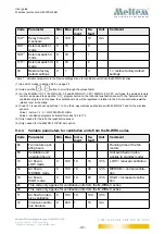
15
Air flow in
HIGH mode
0
100
1
50
m
3
/h
HIGH = increased ventila-
tion
44
Air flow for extract
air in HIGH I mode
0
100
1
70
m
3
/h
Button 4 on the ventilation
unit’s membrane keypad
45
Air flow for supply
air in HIGH I mode
0
100
1
70
m
3
/h
Button 4 on the ventilation
unit’s membrane keypad
11
Air flow for inten
-
sive ventilation
0
100
1
100
m
3
/h
Button 5 on the ventilation
unit’s membrane keypad
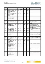
12
Intensive ventila-
tion duration
0
240
1
15
min
Button 5 on the ventilation
unit’s membrane keypad
55
Switch-on delay
for external control
input
0
240
1
1
min
56
Follow-up time for
external control
input
0
240
1
15
min
54
Air flow for extract
air/supply air with
external control
input
0
100
1
60
m
3
/h
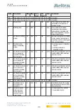
95
(1)
External control
input mode
0
18
1
12
Selected ventilation
program for external control
input
36
Threshold for
humidity control
40
80
1
60
%
Threshold for humidity
control above which the
ventilation unit increases the
ventilation level
37
Min. air flow for
humidity control
0
100
1
10
m
3
/h
0: control for Standby mode
active
38
Max. air flow for
humidity control
0
100
1
60
m
3
/h
39
Threshold for CO
2
control
400 1400 10
(2)
800
ppm
Threshold for CO
2
control
above which the ventilation
unit increases the ventilation
level

