


FOCKE MELER GLUING SOLUTIONS
5-2
MAINTENANCE
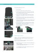
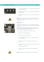
Removing and changing exterior panels:
1. Turn off the melter.
2. Disconnect the compressed air from the machine intake.
3. To remove the casing from the machine, first you have to separate the
electrical cabinet from the tank. To do this, slacken the 1/4 turn screw
as indicated (A) and slide it along the guides.
4. To remove the electrical cabinet door, open the door by turning the
1/4 turn screw as indicated (B), lift the door, turn it and remove the
screws (C).
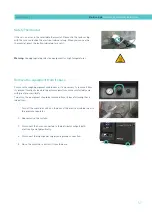
5. To remove the electrical cabinet casing, slacken the screws (D) that
hold it to the base of the machine and the screws (E) that hold it to the
structure of the electrical cabinet.
6. To remove the tank casing, remove screws F and G that hold this casing
to the base of the equipment. The lid and the casing are removed from
the tank at the same time.
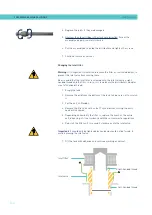
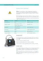
7. The tank lid of 5 and 10 is removed once the tank casing has
been dismantled. It is simply a matter of sliding the shafts at the ends
along the grooves in the casing. (See diagram 1).
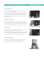
The tank lid of 20 and 35 is removed loosening the side lid
screws (See diagram 2).
8. To assemble the casing, follow the instructions in reverse order.
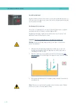
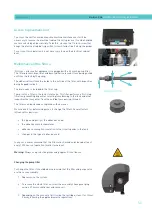
System depressurisation
‘’ series melters are equipped with a safety valve that allows you
to depressurize the system whenever the equipment is pneumatically or
electrically disconnected.
Before disconnecting any hydraulic component or opening any distributor
output, it is necessary to follow these steps:
1. Turn off the machine switch on the door of the electrical cabinet next to
the pressure regulator.
The depressurization valve releases the pressure from the hydraulic
circuit, returning the adhesive to the tank.
2. Purge all applicators that have been used either manually or with
the corresponding program command.
1
2
C
G
F
E
D
D
A
B
Summary of Contents for Micron + 10
Page 10: ...FOCKE MELER GLUING SOLUTIONS TABLE OF CONTENTS This page is intentionally left blank ...
Page 38: ...FOCKE MELER GLUING SOLUTIONS INSTALLATION 3 16 This page is intentionally left blank ...
Page 74: ...FOCKE MELER GLUING SOLUTIONS 4 36 MELTER OPERATION This page is intentionally left blank ...
Page 84: ...FOCKE MELER GLUING SOLUTIONS 5 10 MAINTENANCE This page is intentionally left blank ...
Page 91: ...MA 5162 ENG MICRON PISTON ADHESIVE MELTER ELECTRICAL DRAWINGS 7 1 7 ELECTRICAL DRAWINGS ...
Page 92: ...FOCKE MELER GLUING SOLUTIONS 7 2 ELECTRICAL DRAWINGS This page is intentionally left blank ...
Page 102: ...FOCKE MELER GLUING SOLUTIONS 8 10 PNEUMATIC DIAGRAM This page is intentionally left blank ...
Page 104: ...FOCKE MELER GLUING SOLUTIONS 9 2 SPARE PARTS LIST This page is intentionally left blank ...