M2D-Laser-Scanner with Ethernet-Interface
Manual
HB-M2D-Ethernet-E
Page 17 of 39
www.MElsensor.com
S
S
c
c
a
a
n
n
n
n
e
e
r
r
c
c
o
o
n
n
t
t
r
r
o
o
l
l
s
s
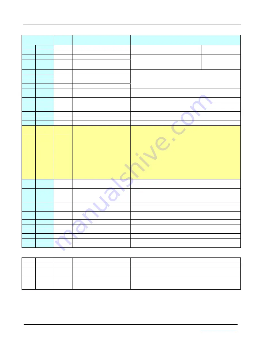
Registers
Hex Dec
Bit
Function Registers
Marked light blue
Remark
0x0
0
6 … 0
Shutter time low
0x1
1
2 … 0
Shutter time high
Shutter time
0= max. 1022 = min. 1023= Laser off
Manual control
0x2
2
6 … 0
Max shutter time low
0x3
3
2 … 0
Max shutter time high
defines limit for the max. shutter.
0 = max. 1022 = min. (single scanner)
Alternate sync meas. not below 130
Automatic control
0x4
4
6 … 0
Start readout pixels
0x5
5
6 … 0
End readout pixels
Value range = 0 … 127. 1 Bit corresponds to 8 pixels
Condition: begin < end, max. is limited automatic
0x6
6
6 … 0
Video gain low
0x7
7
2 … 0
Video gain high
< 256 = +27dB 1023 = 0dB default = 950 = +2,57 dB
value is set after first sending the high byte value
0x8
8
6 … 0
Intensity threshold
1 … 127 intensity threshold value for internal automatic laser
control; factory default = 15
0x9
9
6 … 0
Laser value
1 … 127 value for the laser control (default = 95)
0xA
10
6 … 0
Peak width limit
0 = 0ff; other = peak width limit, max. = 127 pixels
0xB
11
0
FPGA OK LED
0 = on 1 = off
0xE
14
*
Reset position encoder
Reset encoder counter
0xF
15
0
Synchronization
0 = simultaneous measmnt. 1 = alternating measmnt.
0x10 16
0
Adjustment scan, image
0 = scan data 1= complete image (see page 19.)
0x11
17
5 … 0
defines content of status
register
marked yellow
0 = sensor temperature
1 = register content
2 = version electronic board
3 = version camera
4 … 8 = hours counter seconds
9 … 11 = On/Off counter
12 = digital inputs 1 +2 + bit for sensors with mirror
13 = Bit 2 … 9 of Laser control
14 = Revision number example: 3.5xxxx
xxxx is the revision number
15 … 31 = NC
32 … 63 = 32 Byte Eprom Data (see below)
0x12 18
2 ... 0
Select scanner protocol version 0 = Version 1 1 = Version 2 2 = Version 3 3 = Version 4
0x13 19
Reset camera chip
reset hours counter and camera
0x14
20
0 … 2
3
5 .. 4
Do not use!
Measurement control
Field out definition
Bit 0 … 2 is only for Rev.1 hardware
0 = continuous 1 = single shot triggered
00=both fields | 01=only 1
st
. field | 10=only 2
nd
field
0x15 21
0
Laser control
0 = automatic 1 = external (register 0& 1)
0x16 22
0
Linearization
0 = off 1= on default start value = 1
0x17 23
0 … 1
Sampling rate and resolution for
M20D-XF 300 .. 1000 Hz model
0 = 300 Hz; 1 = 500 Hz; 2 = 700 Hz; 3 = 1.000 Hz
0x18 24
Special
Function
Read out status of control registers and FiFO for ISA hardware
0x1B 27
7…0
Peak detection threshold
Default = 10
0x1C 28
*
Reset FiFO
Erases all values in FiFO
0x1D 29
*
Single picture in trigger-mode
Register 0x14 (20) must be set before using trigger
0x1E 30
*
Reset Sensor
set all register values to default
S
S
p
p
e
e
c
c
i
i
a
a
l
l
c
c
o
o
m
m
m
m
a
a
n
n
d
d
s
s
f
f
o
o
r
r
t
t
h
h
e
e
E
E
t
t
h
h
e
e
r
r
n
n
e
e
t
t
v
v
e
e
r
r
s
s
i
i
o
o
n
n
0x1F 31
*
Reset Blue Box
Network Communication is restarted
0x20 32
*
Watchdog test
Watchdog issues reset on Ethernet-Scanner
0x21 33
*
Poll Scanner information
32 re 32 Eprom values set at start-up of the Ethernet
module were sent. Protocol version is set to 0x10 hex.
0x22 34
*
new network settings
Activate new IP address
0x23 35
0
Ethernet Trigger mode
0 = deactivate 1 = activate
when active, read image with register 0x1D (29)
The content of status register 2 is defined by register 0x11 (17). For all values made by more than one Byte, bit 7 is always 0.
This means only 7 Bit are transferred per Byte.
* Each access to the register triggers the function: just send the register address with no parameter.
Accessing the status register 0x11 selects the contents of the sensors status register. This allows to read out the parameters
of sensor temperature, register content, version of electronic board and camera, hours and on/off counters, digital inputs, laser
control, revision number, 32 byte of Eprom data, see the following pages.


