MegaSquirt 2Extra Parallel Installation Manual Download Page 1

Megasquirt 2Extra (V3 board), 1997 Parallel Installation 

Safety instruction from MS2 build manual (http://www.megamanual.com/ms2/V3assemble.htm): 

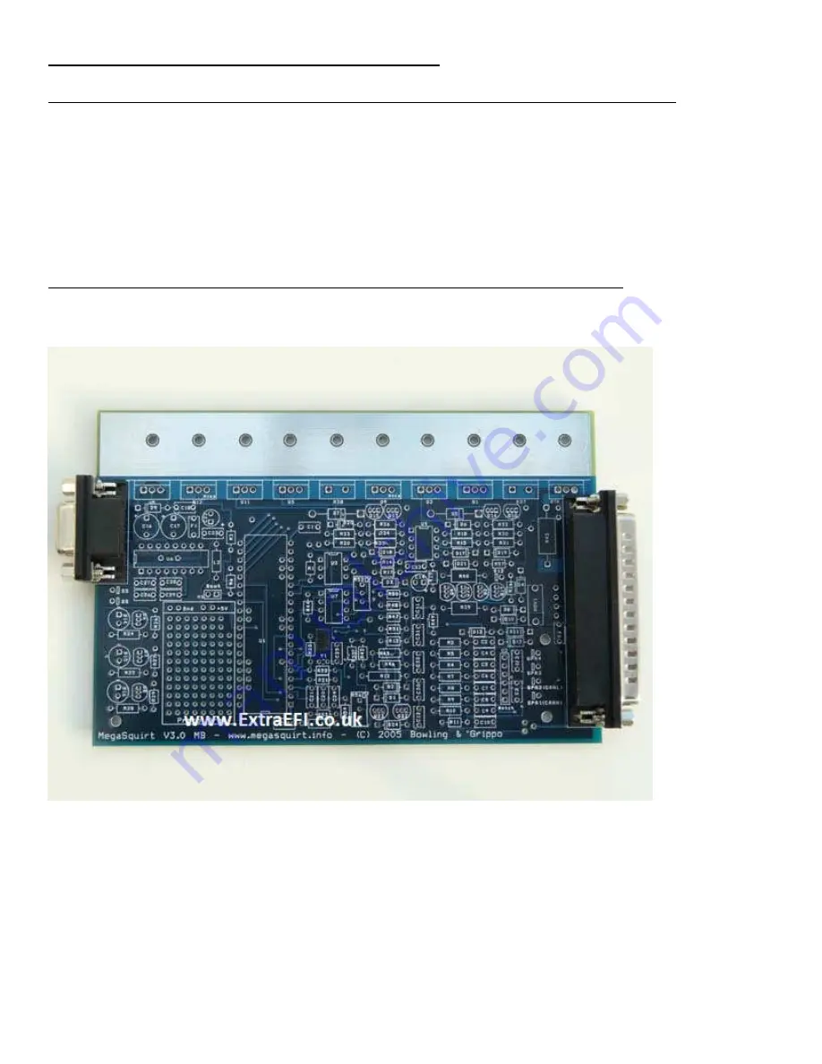
Use an Ohmmeter (digital multi-meter set on resistance) to check the resistance between the three voltage 
regulator holes. The voltage regulator is U5, near the DB9 connector in the top left side of the board (on the 
heat sink). The resistance between any two of these three holes should be infinite. If it is not, contact the 
supplier you bought the kit from. (This test ensures that the 12 Volt supply, 5 Volt internal supply, and ground 
are not shorted together.)  


MS2 Extra build instructions (http://www.msextra.com/doc/ms2extra/build_manual.htm) 

3) Start the build by soldering in the 2 connectors (37pinned and 9 pinned items) 


4) Next get all the bags of resistors together, keeping them in the bags. (R1, etc) 
Find R12, R37, R38, R43, R39 and R57. Put them out of the way, you don’t need any of them, but R43 may 
come in handy later. Solder the holes on the board for R39 so you don't accidentally fit it. (The rest will be fine 
as you shouldn't find these in the parts to fit if you've put them to one side)  
Note from JBPerf.com: If using the external injectors, remove 

R21, R22,R23.


BM Note: If it’s a parallel install, don’t install R4 and R7 or the Coolant and Intake temp signals will be 
incorrect for the stock ECU. Removing these means these inputs won’t work if you’re running on a 
Stimulator. 
5) Now solder all of the rest of the resistors in place. Note: There is no polarity for resistors, so they can fit in 
either way round.
 

Summary of Contents for 2Extra

Page 1: ...htm 3 Start the build by soldering in the 2 connectors 37pinned and 9 pinned items 4 Next get all the bags of resistors together keeping them in the bags R1 etc Find R12 R37 R38 R43 R39 and R57 Put t...

Page 2: ...h these diodes as you may need them FIdle output mods Note D1 may need installing if your using a coil ve triggering setup 8 Now solder the 4 holes up on the main board for D1 and D2 so you don t acci...

Page 3: ...ou re NOT using the coil ve as the trigger input Fuel only find C30 and put it out of the way 14 Solder the 2 holes up on the main board for C30 so you can t fit a capacitor into the holes by accident...

Page 4: ...underneath Solder in MOV1 looks like a big round capacitor Not shown installed in this photo 17 Now find the bag with all the chips in it U6 U3 U7 and U4 Solder these in place be careful to get them...

Page 5: ...tal strip heatsink in place and start fitting the main power transistors remembering Q9 and Q12 have a piece of mica insulation under them to stop them touching the heatsink Note you can put a screw t...

Page 6: ...move about 21 You can now fit all the other components except for those that you put to one side I fit the MAP sensor last don t forget to bolt it in place with the plastic screws then solder it in o...

Page 7: ...component on the heat sink later on in the build Remember that without these current sense resistors there is no over current protection on the injector circuits Note I installed R37 and R38 23 R43 is...

Page 8: ...then put the ve probe on the 0V on the proto area and put the ve probe onto the left pin of U5 top left hand side on heatsink check the voltage on the meter it should be 12V 9V if using a battery if...

Page 9: ...omponents Q4 Q20 and R39 in place Note this gives you a programmable output that can drive a relay e g cooling fan on FIdle Pin 30 of the db37 ii PWM Idle Valve MS1 or MS2 2 3 wired devices need a TIP...

Page 10: ...Hall input covers all inputs like VAST EDIS PIP GM HEI etc See the specific manual for you re engine s input to find out if it s 5V or 12V If in doubt measure the voltage with the engine stopped and...

Page 11: ...e off We could achieve this by using a PNP transistor on the CPU output pin PNPs have the opposite control polarity of NPNs edit no that wouldn t work however since NPNs are already a part of the the...

Page 12: ...S board so Spark A goes to pin 31 and Spark B goes to pin 36 http www miataturbo net megasquirt 18 ms2 standalone stock ignitor 70414 As you can see we re using the natural pullup of the existing LED...

Page 13: ...pinned microprocessor for MS1 or a daughter board for MS2 into the 40 pin connector Plug the ECU into your stim and turn the power on Feel the top row of power transistors if they get hot at all turn...

Page 14: ...picture below shows the modification which connects pin 1 of the NAND gate chip U2 on the MS2 card to pin 4 of the 40 pin header and pin 4 of U2 to pin 5 of the header With that modification pins 3 a...

Page 15: ...location closer to the header pins and more space to solder jumpers The black lines in the schematic below show the new jumpers connection It should be noted also that the CPU pins corresponding to in...

Page 16: ...not interfere with injector channels 1 and 2 The injectors channels 3 and 4 connect to pads originally used for the MS1 clock circuit and require the removal of those components for proper and safe o...

Page 17: ...and should be taken from a fused source from the main relay Signal GND should connect to Megasquirt sensor ground If present Power GND should connect to the engine block along with the other Megasquir...

Page 18: ...rcuit on the prototype area of the mainboard and connect your MAF signal into the case through a spare pin on the DB37 connector e g One of SPR1 2 3 4 if they are free BM Note I chose SPR2 normally al...

Reviews: