


User Manual
Laser Diode Driver
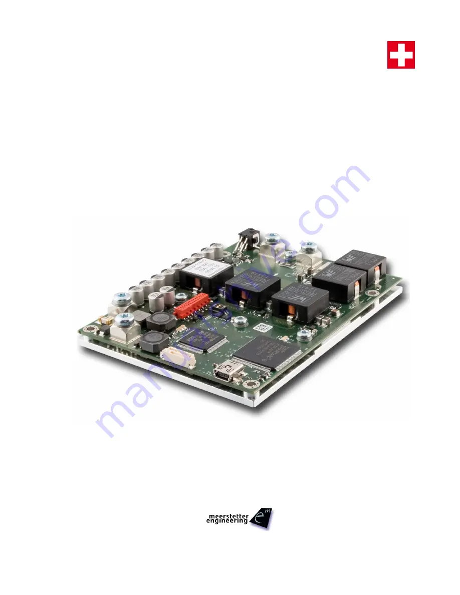
LDD-Family:
LDD-1124
LDD-1121
LDD-1125
Meerstetter Engineering GmbH
Schulhausgasse 12
3113 Rubigen, Switzerland
Phone: +41 31 712 01 01
Email: [email protected]
Website: www.meerstetter.ch
Meerstetter Engineering GmbH (ME) reserves the right to make changes without further notice to the product described herein. Information
furnished by ME is believed to be accurate and reliable. However typical parameters can vary depending on the application and actual performance
may vary over time. All operating parameters must be validated by the customer under actual application conditions.
SWISS MADE
Summary of Contents for LDD-1121
Page 2: ......


