background image


www.procontechnology.com.au

                                                 4                                                             Phone: (03) 98306288                         

3. INSTALLATION, WIRING AND OPERATION 

 
Even the most efficient switched mode DC-DC converter will not function properly if the installation, wiring or connections are 
incorrect. Follow the installation, wiring and connection instructions specified in the data sheet or manual before switching on 
any unit. Also see the document 'Power Supply Cables and Connectors' (Meanwell_Connect_Safety.pdf). 
 
3.1 INSTALLATION 
 
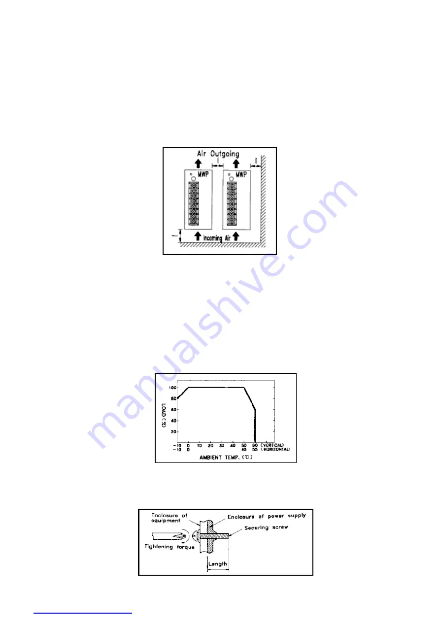
Heat Dissipation 
 
a. Ensure the unit is properly ventilated.  
b. Install the unit in the correct position. Remember 'hot air rises' and ensure correct orientation.  
c. Ensure the unit has proper heat conduction and is not mounted near other heat sources. 
d. When you install two or more units, leave additional space between them for cooling.  
e. Forcing air over the unit will improve heat dissipation. 


Fig. 6 

 
When mounting any device please refer to any notes and temperature derating curves in the specifications. For example with 
DIN rail converters, the minimum installation clearances are: 40mm on top, 20mm on the bottom, 5mm on the left and right 
sides unless the adjacent device is also a heat source then 10-15mm clearances are recommended. 
 
Output Derating 
 
Output power depends on operating temperature. Derate the output of the DC-DC converter according to the temperature 
derating curve shown in the specifications. The Railway DC-DC converter series (RSD) when mounted on an iron plate of 
sufficient size allows for the elimination of any derating up to its' maximum operating temperature of 70°C. Note the output 
power may also need to be derated with low input voltages. Specifications cannot be guaranteed when under-voltage. Some 
units will shut down on under-voltage. 


Fig. 7 

Securing Screws 
 
Always check the specified screw length and tightening torque when attaching to your equipment enclosure. 


Fig. 8 

See the mechanical 
specifications in the data 
sheet. Length L=? is in 
millimetres. 

Summary of Contents for DDR-120B-12

Page 1: ... Fig 2 Not all Meanwell DC DC converters have reverse polarity input protection The simplest form of protection is a fuse and a diode if necessary the user may provide these components externally The latest Meanwell high wattage DC DC converters RSD and DDR series use a MOSFET circuit that tolerates accidental polarity reversal without damaging the unit Also not all DC DC converters have sufficien...

Page 2: ...an result Types of Protection a Foldback Current Limiting The Foldback Current Limiting circuit is designed to linearly decrease both the voltage and current to a level that will prevent the unit from being damaged during overcurrent overload conditions See curve a in Fig 4 b Constant Current Limiting Constant Current Limiting allows the output current to remain stable but reduces the output volta...

Page 3: ...perature condition is removed high ambient temperature and or high load 2 4 OVER VOLTAGE PROTECTION OVP When the output voltage exceeds the rated value by approximately 130 the unit will be protected by the following three possible methods to prevent damage to the components at the load terminals a Shut down the output voltage Reset the DC DC converter by turning it OFF for several seconds and the...

Page 4: ...any device please refer to any notes and temperature derating curves in the specifications For example with DIN rail converters the minimum installation clearances are 40mm on top 20mm on the bottom 5mm on the left and right sides unless the adjacent device is also a heat source then 10 15mm clearances are recommended Output Derating Output power depends on operating temperature Derate the output ...

Page 5: ...that the converter not be mounted until all work has been completed or the vents are covered until the converter is ready to be operated Fig 9 Ground connection Connect the ground terminal of the DC DC converter to the frame of the equipment with regulation size and colour wire to ensure safety and to minimize noise and interference Fig 10 Inrush Current Control Mean Well DC DC converters have lar...

Page 6: ...e able to detect any voltage drop at the load The unit will raise the output until the correct voltage is provided at the load terminals Remote sensing compensates for voltage drops of up to 0 5V Fig 12 Operation in Parallel Power supplies are commonly used in parallel to increase the output current Mean Well s DDR 240 and DDR 480 series are designed for parallel use These power supplies have P an...

Page 7: ...in series to produce higher voltages Two types of series connections are described below For series operation all DC DC converters require floating or isolated outputs a Fig 15 describes a sample setup for separate distinctive loads Protective diodes D1 and D2 below may be necessary with this type of application to protect the units if connection X is lost Fig 15 b Fig 16 illustrates a sample setu...

Page 8: ...pacitors and control the output ripple Their values should be between 47uf and 100uf C2 C4 C5 C6 are high frequency ceramic capacitors and reduce the output noise Their values range from 0 01uf and 0 1uf The value of inductance L1 is 0 5uH to 5uH Surge Voltage Control Fig 18 shows a circuit used to control voltage surges that may be caused by power fluctuations or stray surges due to lightning The...

Page 9: ...Voltage The input voltage of the DC DC converter by design is limited It can be dangerous to apply voltage which is outside of the specified range damage may occur to the unit Always operate it within its specified input voltage range Always check the polarity of the input voltage before applying power Leakage Current The internal noise filter capacitors generate a leakage current within the range...

Page 10: ...d output sides of the DC DC converter Ground Wire Connect the grounding terminal of the unit to the frame of the equipment with a short thick wire Note For DC DC converters integrated into other equipment safety standards differ from country to country Check the standards specifications listed in documents provided by your supplier or relevant government agency when you use a converter inside your...

Page 11: ...ITY 6 1 LIFE CYCLE AND BREAKDOWN DC DC converters have proven to be highly reliable when used in household appliances and industrial products and are highly rated throughout industry The following figure shows the failure rate curve bathtub curve during a typical product life cycle The Early Failure Period to prevent early failure each manufacturer screens out parts or performs aging tests on the ...

Page 12: ...d continuously In this case the frequency of overhauls to the DC DC converter should be as follows Ta is between 40ºC and 45ºC once every three years Ta is between 35ºC and 40ºC once every four years Ta is between 30ºC and 35ºC once every five years Where Ta indicates the ambient temperature of the DC DC converter The above temperature values may differ depending on the type of DC DC converter use...

Page 13: ...of this information for their application We strongly advise all customers to contact us for advice on the most suitable DC DC converter for their needs It is especially important that the correct DC DC converter is used and protective circuits are installed when driving heavily inductive or capacitive loads including motors DC to DC converters and other loads with high inrush current such as lamp...

Reviews: