Meade 50 AZ-T Instruction Manual Download Page 13

- 13 -

and point the telescope at a moderately bright (second or third
magnitude) star, then center the star image in the telescope’s
field-of-view.  With the star centered, follow the method below:

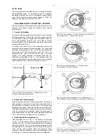
1. Bring the star image slowly out of focus until one or more

rings are visible around the central disc.  If the collimation
was performed correctly, the central star disk and rings will
be concentric circles, with a dark spot dead center within the
out-of-focus star disk (this is the shadow of the secondary
mirror), as shown in Figure 17A.  (An improperly aligned
telescope will reveal elongated circles (Fig. 17B), with an
off-center dark shadow.)

2. If the out-of-focus star disk appears elongated (Fig. 17B),

adjust the primary mirror tilt hex screws of the primary mirror
cell until the circles are concentric on either side of focus.

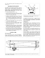
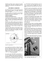
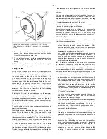
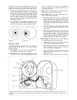
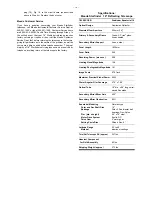
Fig. 18:  The Motor Drive System.  (1) Clutch Adjustment Screws; (2) Back Plate; (3) Clutch Pressure Plate; (4) Worm Gear; (5) Spur Gear; (6)
Worm Block; (7) D.C. Motor; (8) Worm; (9) Red Wire; (10) Motor Plug Connector; (11) Slow-Blow Fuse; (12) Circuit Board; (13) Battery Carrier; (14)
Dust Cover.

Fig. 17A.

Fig. 17B.

harm to your equipment.  This fuse can be replaced by
removing the dust cover to expose the fuse holder on the
back of the control panel.

3. Balance: The telescope may not be properly balanced -

see BALANCING THE TELESCOPE, page 5.

4. Clutch Power Plate:  The clutch pressure plate may be

loose.  To tighten the pressure plate:

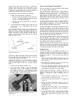
a. Remove the dust cover (14), Fig. 18.  There are five

wires coming off the motor. These wires all lead to one
connector (10), Fig. 18, that plugs into the top corner of
the circuit board, next to the slow blow fuse.  Unplug this
connector (the motor plug) before beginning any work
on the motor.

b. Tighten each of the three clutch pressure plate screws

(1), Fig. 18, slightly until there is sufficient drag to drive
the telescope.

c. Plug the connector back into the top corner of the circuit

board, making sure that all 5 pins on the circuit board
are covered by the connector. The connector should be
oriented so that the wires are leading away from the
board, not crossing over the board.  Note the position of
the red wire (9), Fig. 18.  Replace the dust cover.

5. Worm Block:  The worm block may be out of adjustment.

To eliminate binding in the worm gear system:

a. Remove the dust cover and unplug the motor from the

circuit board (as described above in Step 4a).

b. Loosen the two screws that hold the worm block (6), Fig.

18, to the back plate (2), Fig. 18.  These screws can be
found on the outside of the back plate.

c. Move the worm block until the worm (8), Fig. 18, fits

snugly against the worm gear (4), Fig. 18, with just a
small amount of play.

d. Tighten the worm block screws and connect the motor

Telescope Tracking 

If the telescope does not correctly track a star, check the
telescope's polar alignment (page 8).  If a problem still persists,
check the following:

1. Power Supply:  The motor may not be getting power -

check battery condition and replace if necessary.

2. Slow Blow Fuse:  Your Starfinder is equipped with a slow-

blow fuse (11), Fig. 18, that will sacrifice itself to prevent

1

2

3

4

5

6

7

8

9

10

11

12

13

14

Summary of Contents for 50 AZ-T

Page 1: ...Meade Instruments Corporation INSTRUCTION MANUAL 16 Starfinder Reflecting Telescope ...

Page 2: ...e shortest fraction of a second will cause instant and irreversible damage to your eye as well as physical damage to the telescope itself When observing with the telescope during the daytime do not point the telescope even close to the Sun 1 24 2 3 4 5 6 7 8 9 10 11 12 13 14 16 15 17 18 20 21 22 19 23 ...

Page 3: ...l Panel 5 R A Encoder Port 5 On Off Switch 5 Installing the Batteries 5 12vDC Outlet 6 Collimation of the Optical System 6 Correct Collimation 6 Spider Vane Adjustments 6 Secondary Mirror Adjustments 6 Primary Mirror Adjustments 7 The Viewfinder 7 Focusing the Viewfinder 7 Aligning the Viewfinder 7 Using the Viewfinder 7 Magnification 7 Astronomical Observing 8 Celestial Coordinates Declination Ri...

Page 4: ...ft after the lighter counterweight CAUTION Be sure to secure the counterweight safety washer 11 Fig 1 onto the end of the declination shaft by placing the washer at the end of the shaft and replacing the panhead screw The counterweights should never be removed with the optical tube in place 5 Attaching the Focuser Assembly To install the focuser assembly first lay the optical tube flat on a floor ...

Page 5: ... advantage if the telescope is to be frequently disassembled or transported CONTROL PANEL R A Encoder Plug The R A encoder plug 4 Fig 2 is used if the Magellan I Computer System is purchased for the Meade 16 Starfinder Details of how this additional encoder plug is used can be found in the Magellan I instruction manual The Magellan II system requires a hardware upgrade and different control panel ...

Page 6: ...4 Secondary Mirror Assembly 1 Spider Vanes 2 Tilt Screws 3 Secondary Mirror Holder Face on view Edge on view 1 3 2 2 Spider Vane Adjustments Looking down the open end of the telescope tube check to see if the secondary mirror system is centered in the optical tube If the assembly is off center loosen one of the spider vane adjustment lock knobs while unscrewing the opposite knob Only make adjustme...

Page 7: ...s MAGNIFICATION The magnification or power at which a telescope is operating is determined by two factors the focal length of the eyepiece employed and the focal length of the telescope The Meade Starfinder telescope is supplied with one eyepiece as standard equipment The focal length of the eyepiece 25mm is printed on its side Telescope focal length is roughly speaking the distance that light tra...

Page 8: ...e celestial equator Objects located further and further east of the prime Right Ascension grid line 0hr 0min 0sec carry increasing R A coordinates All celestial objects are specified in position by their celestial coordinates of Right Ascension and Declination The telescope s Dec and R A setting circles 8 and 17 Fig 1 may be dialed to the coordinates of a specific celestial object which may then b...

Page 9: ...to the monthly star charts presented in astronomy magazines such as Sky Telescope and Astronomy will be helpful With these aids and with a little experience at the controls of the Starfinder you will soon be exploring the surface of the Moon the planets of our Solar System and the incredible assortment of star clusters galaxies and nebulae that lie beyond The Motor Drive The DC drive system on you...

Page 10: ...telescope be precisely aligned with the pole The setting circles may also be utilized in the absence of a power source for the motor drive In this case however it is necessary to manually reset the R A of the object being observed just before moving the telescope to the next object Observing Tips To enjoy the 16 Starfinder telescope to its fullest potential follow these recommendations 1 Let the t...

Page 11: ...STROPHOTOGRAPHY Your reflecting telescope can be used as a powerful astrophotographic lens with the addition of virtually any 35mm Single Lens Reflex SLR camera body The Basic Camera Adapter see OPTIONAL ACCESSORIES this page and T Mount for your specific brand of SLR camera serve as the link between telescope and camera The Starfinder Equatorial Telescope design allows the user to take short expo...

Page 12: ...the user to make fine micrometric adjustments in Declination 140 2x Barlow Lens The Barlow Lens or Telenegative Amplifier is a convenient accessory used to increase the effective magnification of any given eyepiece The Barlow Lens is inserted into the focuser and accepts all standard 1 25 O D eyepieces 607 Power Cord This 25 ft power cord allows the user to power the Starfinder Equatorial Telescop...

Page 13: ...18 There are five wires coming off the motor These wires all lead to one connector 10 Fig 18 that plugs into the top corner of the circuit board next to the slow blow fuse Unplug this connector the motor plug before beginning any work on the motor b Tighten each of the three clutch pressure plate screws 1 Fig 18 slightly until there is sufficient drag to drive the telescope c Plug the connector ba...

Page 14: ... Meade Starfinder TM 16 Reflecting Telescope TELESCOPE Starfinder Equatorial 16 Optical Design Newtonian Reflector Diameter Clear Aperture 406mm 16 Primary Secondary Mirrors Grade A Pyrex glass fine annealed Secondary Mirror Support 4 vane steel Focal Length 1830mm Focal Ratio f 4 5 Resolving Power arc secs 0 28 Limiting Visual Magnitude 15 6 Limiting Photographic Magnitude 18 1 Image Scale 0 79 i...

Page 15: ...e This warranty applies to the original purchaser only and is non transferable Meade products purchased outside North America are not included in this warranty but are covered under separate warranties issued by Meade international distributors RGA Number Required Prior to the return of any product or part a Return Goods Authorization RGA number must be obtained from Meade by writing or by calling...

Page 16: ...ruments Corporation World s leading manufacturer of astronomical telescopes for the serious amateur 6001 Oak Canyon Irvine California 92620 949 451 1450 Fax 949 451 1460 www meade com Ver 0698 Part no 14 0221 50 ...

Reviews: