background image


Configuring the terminal in the Service application 

Configuring the "GPS TILT-Module" terrain compensation 


30302710-02-EN 

V7.20160121 

39 


Format of correction signal for the SMART-6L DGPS/GLONASS receiver. 
Only appears when "RTK radio" or "RTK GSM" correction signals have been selected. 
Possible values: 
  ▪  RTCM V3 
  ▪  CMR/CMR+ 
  ▪  RTCA 
For the correction signal format which you must select, please refer to your correction service. 
Terrain compensation 
The GPS TILT-Module terrain compensation is configured using this parameter. 
You can order the terrain compensation from Müller-Elektronik with the following item number: 
30302495. 

RTK license for SMART-6L 

You will need a SMART-6L DGPS/GLONASS receiver and RTK license in order to work with RTK 
correction signals. 
The RTK license is inserted by Müller-Elektronik. You will need to either order a license at the same 
time as you order the receiver, or send in your receiver. 


Configuring the "GPS TILT-Module" terrain compensation 


  The "GPS TILT-Module" terrain compensation is connected. 


  The tractor is positioned on level ground. 


  The driver of the external ME LightBar is deactivated. 

1.  If any additional devices (e.g. ME LightBar) are connected to the cable between the terminal and 

the tilt module, disconnect them. The tilt module must be connected directly to the terminal. After 
the tilt module has been configured, these additional devices must be reconnected. 

2.  Measure the distance between the GPS receiver and the ground surface. 
3.  Switch on the terminal. 
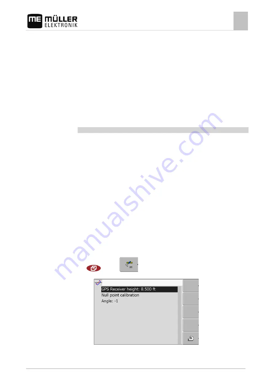
4.  Switch to the tilt module configuration screen: 

| Service | 

| Tilt module 


  The following screen appears:  


5.  Enter the distance between the GPS receiver and the ground surface in the line "GPS receiver 

height". 

7.6 

Procedure 

Summary of Contents for TRACK-Guide II

Page 1: ...nstallation and operating instructions TRACK Guide II Version V7 20160121 30302710 02 EN Read and follow these operating instructions Keep these operating instructions in a safe place for later reference ...

Page 2: ...umber 30302710 02 EN As of software version 04 10 04 Original language German Müller Elektronik GmbH Co KG Franz Kleine Straße 18 33154 Salzkotten Germany Phone 49 0 5258 9834 0 Fax 49 0 5258 9834 90 Email info mueller elektronik de Homepage http www mueller elektronik de Document Copyright ...

Page 3: ... cab 12 4 1 1 Terminal ports 13 4 1 2 Mounting the GSM antenna 13 4 2 Connecting the terminal to voltage supply 14 4 3 Connecting the terminal to the ISOBUS 14 4 4 SIM card 15 4 4 1 Inserting the SIM card 15 4 5 Connecting the ISO printer to the terminal 16 4 6 Connecting the ME LightBar to the terminal 17 4 7 Connecting the on board integrated display controller to the terminal 17 4 8 Connecting ...

Page 4: ...he camera 41 7 9 Configuring the joystick button allocations 42 7 10 Adjusting the brightness for day or night mode 45 7 11 Enabling and disabling applications 45 7 12 Activating licenses for full versions of the software 46 7 13 Setting the purpose of the terminal 47 7 14 Deleting files from the USB memory device 48 7 15 Deleting pools 48 7 16 Activating the Diagnostics function 49 7 16 1 Diagnos...

Page 5: ...ing target rates via ASD 67 11 File Server application 70 12 Maintenance and servicing 71 12 1 Servicing and cleaning the terminal 71 12 2 Disposing of the unit 71 12 3 Instructions on retrofitting 71 12 4 Checking the software version 72 12 5 Technical specifications 72 12 5 1 Technical specifications of the terminal 72 12 5 2 Pin assignment of port A 73 12 5 3 Pin assignment of port B 74 12 5 4 ...

Page 6: ...rmful to human health You should therefore follow the instructions below when the terminal is fitted with a GSM modem If you wear a medical device ask your doctor or the device manufacturer how to proceed in order to prevent risks Medical devices such as pacemakers or hearing aids may be sensitive to the radio signal of the built in GSM modem If you wear a pacemaker keep the terminal away from the...

Page 7: ...se and cautious manner in order to produce optimum work results There are some actions that need to be performed in several steps If there is a risk involved in carrying out any of these steps a safety warning will appear in the instructions themselves Safety instructions always directly precede the step involving risk and can be identified by their bold font type and a signal word 1 NOTICE This i...

Page 8: ...held liable for any personal injury or property damage resulting from such non compliance All risk arising from improper use lies with the user All applicable accident prevention regulations and all other generally recognized safety industrial and medical standards as well as all road traffic laws must be observed Any unauthorized modifications made to the equipment will void the manufacturer s wa...

Page 9: ...o identify different operating instructions Type of depiction Meaning 1 2 Actions that must be performed in succession Result of the action This will happen when you perform an action Result of an operating instruction This will happen when you have completed all steps Requirements In the event that any requirements have been specified these must be met before an action can be performed Layout of ...

Page 10: ...serial interface In this way you can also use the GPS signal for machines which are not ISOBUS compatible You can transfer target rates to the on board integrated display controller or switch sections The data is sent using the LH5000 or ASD protocols If you want to use the ASD protocol you must activate the ASD Protocol license You can test the following application for 50 hours free of charge SE...

Page 11: ...e sticker on the back of the terminal On this sticker you can find all the information you need to definitively identify the product Have these details ready when you contact Customer Services Abbreviations on the rating plate Abbreviation Meaning Software version You can see the installed software version on the Start Screen of the Service application Hardware version Operating voltage The termin...

Page 12: ...ver port C 4 Connect the working position sensor optional port B Mounting the terminal in the tractor cab NOTICE Electromagnetic interference The operation of the terminal may be impaired by electromagnetic waves emitted by other farm equipment Mount the terminal at least 1 m away from the radio antenna or from a radio device 1 Screw the bracket to the terminal 2 Mount the terminal with the bracke...

Page 13: ...or connection of ISOBUS basic equipment or voltage supply with TRACK Guide II Covering cap for USB port Prevents dust from entering the USB socket Port B See section Pin assignment of port B 74 SIM card slot Port for analog camera Only for terminals with a GSM modem installed Mounting the GSM antenna WARNING Electromagnetic waves These can interfere with other equipment This also affects medical d...

Page 14: ...ge supply This is how you connect the terminal to voltage supply 1 Connect the power cable included in the delivery to port A of the terminal 2 Connect the power cable on the other side to 10V 30V the vehicle s electrical system Connecting the terminal to the ISOBUS If you purchase the ISOBUS UT app in order to be able to also operate ISOBUS job computers with a terminal you must connect this to t...

Page 15: ... will not need any SIM card You must purchase the SIM card from your mobile phone provider Select a mobile phone provider that can guarantee good mobile phone reception on your fields A good connection is required in order for work with the farmpilot portal to run smoothly The SIM card must meet the following requirements It must be GPRS capable It must be PIN free Inform your mobile phone provide...

Page 16: ...llation the chip on the card must be in contact with the circuit board The card must be positioned as shown in the picture 6 Shut the card holder 7 Press the card holder lightly onto the circuit board until it clicks into place on the right hand side 8 CAUTION Tighten the screws but not too tight otherwise the cover might be damaged 9 Screw the cover back on Make sure that the rubber seal is posit...

Page 17: ... data and guidance lines that are provided by the TRACK Leader app This is why you need the TRACK Leader App to be able to use the ME LightBar External LightBar Connector for connection to the terminal Plug for connecting a GPS receiver Serial port RS232 After connecting an external LightBar to the terminal you must activate 40 it Connecting the on board integrated display controller to the termin...

Page 18: ...ard integrated display controller manufacturer for this On board display controller Null modem cable Adapter cable Available as a set with Cable 3 item number 3032254800 Port B on the terminal When using an Amatron3 or Amatron as on board integrated display controller you will only need a traditional null modem cable Amatron3 and Amatron are on board integrated display controller from Amazone Conn...

Page 19: ...tial start up it can take approx 30 minutes until the GPS Receiver has reception At subsequent start ups it will only take approx 1 2 minutes The GPS receiver is mounted on the roof of the tractor You have activated a suitable driver 1 Switch off the terminal 2 Guide the connection cable from the GPS receiver into the cab 3 CAUTION Ensure that the cable is not laid across sharp edges or at risk of...

Page 20: ...ket to 3 pole 31302497 You can also connect the terminal to the signal socket Cable to the signal socket Hardware ver sion of the terminal Connections Connection Item num ber From 3 0 0 7 pole to 9 pole socket Cable direct to the signal socket Transfers the speed PTO revolution working position 30322548 All 3 pole from the adapter cable dependent on the hardware version to 7 pole Cable to the sign...

Page 21: ...in the assembly instructions of the camera manufacturer 2 Connect the camera to the cable harness 3 CAUTION When laying out the cable harness you should ensure that no kinks form in the cable and that no one can trip over the laid out cable 4 Connect the junction of the cable harness to a power source 12V Müller Elektronik offers different plugs for this purpose which you can connect to the cable ...

Page 22: ...l Control with the rotary knob may vary slightly between the different applications You can use the rotary knob to perform the following actions Turning the rotary knob Move the cursor up and down Change a parameter value Pressing the rotary knob Click on the selected line Activate parameter Confirm input Function keys Operating the function keys is the same across all applications Performing the ...

Page 23: ... is how you start the terminal for the first time You have mounted and connected the terminal 1 Switch on the terminal 2 Wait for approx 15 seconds until all applications have been loaded 3 Open the Selection menu application The following screen will appear 4 In the selection menu you can select which application you wish to display next 5 Select the Service line The Service line must be framed b...

Page 24: ...g Activate the driver of the GPS receiver 35 Configure the GPS receiver 36 Input the position of the GPS receiver only when also using SECTION Control 60 Once you have made these settings the terminal is ready to operate Note however that you will need to configure the TRACK Leader and FIELD Nav applications in detail To do this read the instructions for these applications The number of settings i...

Page 25: ...sure that no danger is posed to people or property When you press a function key the function operation depicted on the function icon will be performed Using the function keys Function icon Depiction of an available function Function key Performs the function depicted on the function icon When you press the function key the function depicted on the function icon will be activated If not function i...

Page 26: ...e data The data input screen has been opened 1 Select the desired character 2 Click on the selected character 3 When all characters have been entered select the OK symbol with the rotary button and click The input will be applied Using two terminals The following table will tell you which settings you need to configure to be able to use two terminals and the chapters in which these are described T...

Page 27: ... 5 30302710 02 EN V7 20160121 27 Parameter Chapter Login as ISOBUS UT Setting the purpose of the terminal 47 Connection with ISOBUS TC Configuring the parameters for a vehicle profile 54 List of connections Configuring the list of connections 64 ...

Page 28: ... The display is split into the following sections Function icons left and right Applications section in the middle between the function icons Sections in the selection menu Name of an application ISO ID of the application ISO name of the application Function icons on the left Select an application which will later be displayed in the header Selection The selected application is displayed on the ma...

Page 29: ... Segmentation of the display The display of the terminal is split into two sections A different application is displayed in each section This allows you for example to control the tractor on the field and monitor the field sprayer at the same time This means that you will not need an additional terminal Segmentation of the display Header informative section The header allows you to display informa...

Page 30: ...Opening applications in the selection menu Segmentation of the display 30 V7 20160121 30302710 02 EN Function icon Function Swap applications between the header section and the main section of the display ...

Page 31: ...he rotary knob Version number Name of the terminal and version of the installed software Function icons section Icons that can be pressed on this screen Controls in the Service application The Service application is controlled using the rotary knob and the function buttons Some of the function icons explained here will only appear if a specific function is activated This limits the information sho...

Page 32: ...ttons on a joystick with functions Driver Auxiliary2 is activated Icons in the Service application You will find the following icons in the Service application Function is activated Function is deactivated Changing the language When you switch on the terminal for the first time the text may appear in a foreign language in German If you change the language in the Service application you also change...

Page 33: ... Language 6 Select the abbreviation of your language 7 Press The following message will appear Restart the terminal 8 Press The language in the Service application will be changed Language will be changed in other application only after a terminal restart 9 Restart terminal The language in other applications will be changed Basic settings The basic settings include Language Time Measurement units ...

Page 34: ...off 0 day mode is activated 1 night mode is activated Volume Adjust volume Date time Date Setting current date Time Setting current time Time zone 0 Time zone Greenwich Mean Time GMT 1 GMT 1 hour Germany 1 GMT 1 hour Language Selecting language Measurement units Metric Displays all units in metrical system Imperial Displays all units in imperial system US Displays all units in US system Keyboard b...

Page 35: ...he terminal The receiver will be directly configured in the PSR application A100 A101 Driver for the Müller Elektronik A100 and A101 GPS receivers For receivers which are connected to the serial interface Standard Driver for unknown GPS receivers For receivers which are connected to the serial interface This driver is activated by default The connected GPS receiver cannot thus be configured AG STA...

Page 36: ...ring the GPS receiver The internal software for each GPS receiver must be configured You can configure the following GPS receivers offered by Müller Elektronik via the terminal A100 A101 AG STAR SMART 6L All other GPS receivers must be configured in accordance with their manufacturer s instructions Function icon Function Reset the configuration of the DGPS receiver to default values Display DGPS c...

Page 37: ...l of the additional devices that you had disconnected for the configuration Parameters for the GPS receiver Baud rate Only appears when the Standard driver is selected Setting for the speed at which the GPS receiver sends data to the terminal The parameter sets the baud rate for the terminal Satellite 1 and Satellite 2 Satellite 1 primary DGPS satellite The DGPS receiver will connect to this satel...

Page 38: ...orrection signal for the DGPS receiver The correction signals which are available is dependent on the activated driver Possible values For the A100 A101 driver WAAS EGNOS Correction signal for Europe North America Russia and Japan E DIF Internal calculation of correction data Only functions with a special version of the A100 DGPS receiver item no 30302464 This receiver is no longer sold by Müller ...

Page 39: ...s The RTK license is inserted by Müller Elektronik You will need to either order a license at the same time as you order the receiver or send in your receiver Configuring the GPS TILT Module terrain compensation The GPS TILT Module terrain compensation is connected The tractor is positioned on level ground The driver of the external ME LightBar is deactivated 1 If any additional devices e g ME Lig...

Page 40: ...tion Activating an external LightBar If you connected an external LightBar to the terminal you must activate it To activate the external LightBar you must first activate its driver You can order the external LightBar from Müller Elektronik with the following item number 30302490 1 Switch to screen Driver Service Driver The following screen will appear 2 Click on LightBar The installed drivers will...

Page 41: ...ltural implement In certain situations the camera image may appear on the screen with a delay The delay depends on the respective use of the terminal and can also be affected by external factors and devices WARNING Accident due to delayed image transmission Rapidly moving objects may be detected too late Do not use the camera as an aid for steering the vehicle Do not use the camera in road traffic...

Page 42: ...table sensor Saving camera settings Exiting camera You can press the function keys even if the camera is set to full screen mode You have connected and activated the camera 1 Switch to the Camera screen Service The following screen will appear 2 Use the function keys to control the camera Configuring the joystick button allocations The terminal offers you the possibility of assigning the functions...

Page 43: ...Elektronik multi function grip MFG LED colour position of the side switch on the multi function grip Multi function grip version Button to which a function is assigned Multi function grip software version Other buttons Function icon Meaning Version information Deletes all assignments Deletes the marked assignment Confirms all assignments To activate the driver for this function 1 Switch to the Dri...

Page 44: ...d ISOBUS job computer This is only an example 2 Select the function which you wish to assign to a button The following screen will appear The content of the screen will depend on the software of the connected joystick 3 Select the button to which you want to assign the selected function This is only an example 4 Exit the screen 5 Restart the terminal After restarting a screen with an overview of t...

Page 45: ...ently active you can use one of the function icons Activate day mode Activate night mode The brightness of the display will be adjusted immediately Enabling and disabling applications In the Service application you can activate and deactivate other applications that are installed on the terminal The applications are installed in packages in so called plug ins A plug in can contain several applicat...

Page 46: ...tart terminal All activated plugins will appear in the selection menu Activating licenses for full versions of the software Several applications are pre installed on the terminal which you can use for trial purposes for up to 50 hours After this time has elapsed they will be automatically deactivated The amount of free usage time remaining is shown in brackets next to the name of the application T...

Page 47: ...pear next to the application on the Licenses screen The application is activated You can use the application without any restrictions Setting the purpose of the terminal If you use more than one terminal you can decide how you want to use this terminal The following options are available to you Login as ISOBUS UT Activate this parameter if you want the ISOBUS job computer to be displayed on the te...

Page 48: ...ck on USB The Screencopy and Taskdata folders will appear If these folders fail to appear it is because you did not create them on the USB memory device 3 Click on the desired folder The contents of the folder will be displayed A folder may either contain files or further folders If nothing is displayed the folder is empty 4 Select the files to be deleted 5 Delete file red Deleting file Deleting p...

Page 49: ...der The contents of the folder will be displayed The names of the folders are the ISO IDs of the applications whose temporary data they store 4 Select the desired file 5 Delete file Deleting file 6 Restart terminal Activating the Diagnostics function To activate the Diagnostics function you must first activate its driver 1 Switch to the Driver screen Service Driver The following screen will appear...

Page 50: ...of the screen being displayed If an error occurs when you are using the terminal Customer Services may ask you to capture a screenshot A screenshot can be emailed to Customer Services Email address service mueller elektronik de sent to the farmpilot portal provided you have activated the farmpilot portal Configuring the screenshots function You have activated the Diagnostics function 49 1 Start th...

Page 51: ...that logs the data exchange between the terminal and the connected jobcomputers Customer Services can use the logged data for diagnostic purposes should any errors arise in the system If an error occurs when using the terminal Customer Services may ask you to activate the CAN Trace function Only activate this function if prompted to do so by Customer Services 1 Switch to the CAN Trace settings scr...

Page 52: ...y that the file StartupTrace txt exists on the USB memory device 11 If this file is missing you must run the CAN Trace function again 12 Email the StartupTrace txt file to Customer Services If you chose Portal as the storage location this file will have been sent automatically Activating the ISO printer In order to activate the ISO printer you must activate its driver 1 Switch to the Driver screen...

Page 53: ...ication allows you to Create a profile for each vehicle with specific settings Input the sensors which are mounted on the vehicle Input the position of the GPS receiver If you are using a self propelled machine you can simply enter the position of the GPS receiver 60 After launching the Tractor ECU application the following screen will appear Tractor ECU application start screen Main area Displays...

Page 54: ...sor Function icon Meaning Add a vehicle profile Vehicle profile cannot be deleted Delete the vehicle profile Return 1 Call up the Tractor ECU application Tractor ECU 2 Call up the list of vehicles 3 Add a new vehicle profile A new vehicle profile appears on the screen You can now configure the parameters of the new vehicle profile Configuring the parameters for a vehicle profile In a vehicle profi...

Page 55: ... terminal Calibrate the working position sensor A hitch sensor front or a hitch sensor rear is used to measure the working position The sensor is connected to the terminal 1 Call up the Tractor ECU application Tractor ECU 2 Call up the list of vehicles 3 Select the vehicle profile 4 Modify the required parameters You can also change the name of the vehicle profile Parameters in a vehicle profile O...

Page 56: ...dar sensor is connected to the terminal The radar sensor must be calibrated 58 GPS receiver The speed is calculated using GPS Unknown sensor via CAN A wheel sensor or a radar sensor is connected to the terminal via CAN Radar sensor via CAN A radar sensor is connected to the terminal via CAN Wheel sensor via CAN A wheel sensor is connected to the terminal via CAN PTO revolution Configuring the PTO ...

Page 57: ...the terminal via CAN Direction You can use these parameters to configure whether the terminal can receive a direction signal and the source from which it originates When a direction signal is present the TRACK Leader application can correctly mark the vehicle movement when travelling in reverse Possible values deactivated No direction sensor is connected to the terminal If another ISOBUS device tr...

Page 58: ...ractor ECU after working with a non ISOBUS implement to not always to transfer the working width Calibrating the speed sensor When calibrating the speed sensor using the 328 085ft 100m method determine the number of impulses which the speed sensor encounters over a distance of 328 085ft 100m If you know the number of impulses for the speed sensor you can also input this manually You have measured ...

Page 59: ...an analog working position sensor which measures the height of the hitch linkage as a percentage digital Use this option if the sensor mounted on your equipment is compatible with the Standard ISO 11786 The sensor is connected to the terminal via the signal socket ME sensor Y You are using a working position sensor provided by Müller Electronik The sensor is connected to the terminal You have conn...

Page 60: ...PS receiver in the Machine profile screen of the TRACK Leader application If you use TRACK Guide II with a SECTION Control box you must enter the position of the GPS receiver here In order to enter an accurate position for the GPS receiver you must measure the distances of the GPS receiver from the longitudinal axis and from the so called attachment point 61 When entering distances please note tha...

Page 61: ...ve input the position of the GPS receiver for the selected vehicle profile For machines fitted with an ISOBUS job computer On the following illustration distances are marked which must be measured for each different machine GPS receiver for ISOBUS machines Attachment point for mounted or trailed implements GPS receiver Mounted or trailed implements Self propelled machines y Distance between the lo...

Page 62: ...ameter Offset Y To determine the distances for self propelled machines with an ISOBUS job computer The jobcomputer of the farm equipment in use is connected to the terminal In the jobcomputer the geometry of the farm equipment is configured 1 Input 0 inch as parameter Offset X 2 Measure the distance between the longitudinal axis of the machine and the GPS receiver 3 Input the measured distance as ...

Page 63: ...job computer In this way you do not have to worry about inputting the target rates ISOBUS TC documents work duration and the persons implements and resources involved Adjusting how you use ISOBUS TC First of all you must decide how you will use the ISOBUS TC application The operation of ISOBUS TC and TRACK Leader is dependent on this setting There are two scenarios in which you can use ISOBUS TC U...

Page 64: ... driving and section switching possible The farm equipment must be ordered consecutively from the front to the rear when viewed in the direction of travel Tractor ECU of the terminal Name of the job computer Connectors between the ME Tractor ECU application and ME_ISO_Spritze The geometries of this equipment is transferred to SECTION Control Not all of the equipment in the list must be connected J...

Page 65: ...automatically In particular when the ME terminal is the only unit which contains the tractor geometry see Entering the position of the GPS Receiver 60 It can however still be necessary to set the list of connection manually in the following instances If a tractor job computer Tractor ECU in which the tractor geometry is saved is mounted as an independent job computer on the tractor In this instanc...

Page 66: ...ufacturer On board dis play controller Software version Baud rate RAUCH Quantron A V1 20 00 9600 RAUCH Quantron E V3 51 00 9600 RAUCH Quantron E2 V2 10 00 9600 RAUCH Quantron S V3 90 00 9600 RAUCH Quantron S2 V1 00 05 9600 ME Spraylight V02 00 10 9600 Only on board integrated display controllers are listed for which we were able to determine that the serial interface was functional Results may dif...

Page 67: ... two ways As a shp file in the TRACK Leader application As part of a ISO XML task if you are using the ISOBUS TC application and a FMIS For more information please refer to the TRACK Leader and ISOBUS TC operating instructions Switching sections and transferring target rates via ASD Tested on board integrated display controllers Manufacturer On board dis play controller Software version Baud rate ...

Page 68: ...r you need to activate the ASD protocol on the on board integrated display controller If yes you have activated the protocol 1 Connect the on board integrated display controller to the terminal 17 2 Switch on the terminal 3 Call up the SerialInterface application SerialInterf 4 Open the list of implement profiles 5 Add a new implement profile A new implement profile appears on the screen 6 Configu...

Page 69: ...15 Back 16 Activate the implement profile 17 Press and confirm to save the implement profile 18 Restart terminal Further steps You have set up the serial interface You must now configure the applications of the terminal In the TRACK Leader application 1 Activate the SECTION Control parameter under Settings General 2 Configure the section switching in Settings SECTION Control 3 Load a prescription ...

Page 70: ... All ISOBUS implements can access this folder and write or read data there The folder has a maximum disk space of 5 MB If you want to copy files to the terminal these must be on your USB memory device in the Fileserver folder 1 Call up the Fileserver application Fileserver The application starts screen will appear 2 Press 3 Copy files from the USB memory device to the terminal Import 4 Copy files ...

Page 71: ...mponents make sure first of all that the retrofitted electrical and electronic components comply with the current version of the EMC Directive 2004 108 EC and carry the CE marking When retrofitting a machine with electrical and electronic farm equipment and or components connected to the vehicle s electrical system it is your own responsibility to check whether the installation causes interference...

Page 72: ...pplication Service 2 The following screen will appear 3 The software version can be found below the ME logo Technical specifications Technical specifications of the terminal Parameter Value Operating voltage 10 30 V Operating temperature 20 70 Storage temperature 30 80 Weight 1 3 kg Dimensions W x H x D 220 x 210 x 95 mm Protection class IP 54 in accordance with DIN 40050 15 EMC In accordance with...

Page 73: ...ptional Pin assignment of port A Port A is a 9 pin D sub port of the ISO agricultural machinery interface CAN Pin no Signal Pin no Signal 1 CAN_L 6 Vin1 GND 2 CAN_L1 7 CAN_H1 3 CAN_GND1 8 CAN_EN_out2 4 CAN_H 9 Vin1 5 CAN_EN_in Legend Vin voltage supply Vin ground 1 Signals marked with 1 correspond to the CiA assignment CAN in automation Both signals CAN_L and CAN_L1 and or CAN_H and CAN_H1 are lin...

Page 74: ...llowing purposes depending on its assignment Purpose Pins used As second CAN interface 7 9 As second serial interface 2 3 4 5 As signal input for two digital and one analog signal 1 5 6 8 Pin assignment of port B Pin no Signal Pin no Signal 1 Wheel sensor1 6 PTO2 2 RxD 7 CAN_H 3 TxD 8 Working position sensor3 or Reverse signal for determining the driving direction 4 Voltage supply for GPS receiver...

Page 75: ...voltage for the GPS Receiver Compare the terminal voltage to the allowable voltage for the GPS Receiver Compare the pin assignment Only connect the GPS Receiver to the terminal if the voltage range and pin assignment of both devices don t differ from each other Pin assignment of port C Pin no Signal 1 DCD 2 RxD 3 TxD 4 Voltage supply for GPS receiver1 5 GND 6 DSR 7 RTS 8 CTS 9 RI 5 V Legend 1 The ...

Page 76: ...nd 2 Ports 1 and 2 are used to connect an analogue camera The pin assignment is identical for both ports Ports 1 and 2 are 5 pin A encoded M12 sockets Please refer to the following table for the pin assignment Pin assignment of the socket in the terminal Pin assignment of the connector Pin Signal 1 Pin is exclusively intended for use by ME do not connect anything 2 GND 3 Pin is exclusively intende...

Page 77: ...Notes 13 30302710 02 EN V7 20160121 77 Notes 13 ...

Reviews: