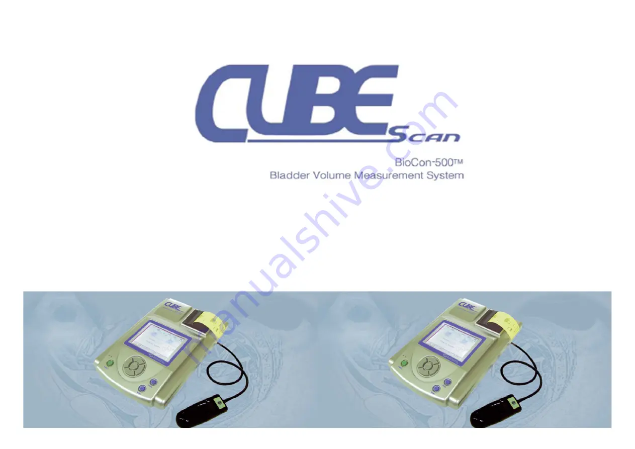
SERVICE TRAINING
Mcube Technology Co., Ltd.
www.mcubetech.co.kr
Page 1: ...SERVICE TRAINING Mcube Technology Co Ltd www mcubetech co kr...
Page 2: ...o kr 2 BioCon BioCon BioCon BioCon 500 Service Training 500 Service Training 500 Service Training 500 Service Training 1 General System 2 System Configuration 3 System Setup 4 Module Test 5 Troublesho...
Page 3: ...www mcubetech co kr 3 PRINCIPLES 1 Gain Lateral Position ultrasonic reflections 3 dimensional scanning abstract bladder wall 125mL calculate bladder volume i 0 i n 1 1 General General General General...
Page 4: ...Measuring ultrasonic reflections on multiple planes 3 dimensional scanning Calculates the patient s bladder volume with multiple planes 3 dimensional images more accurate than conventional 2 dimension...
Page 5: ...www mcubetech co kr 5 2 System Configuration 2 System Configuration 2 System Configuration 2 System Configuration System block diagram Connection diagram Device disassembly...
Page 6: ...www mcubetech co kr 6 2 System Configuration 2 System Configuration 2 System Configuration 2 System Configuration System block diagram...
Page 7: ...ation Connection diagram Control Board J4 Connection Board JP3 JP2 JP1 JP5 JP4 JP6 JP3 JP2 JP1 Analog Board JP5 JP4 JP101 JP2 JP1 JP3 Charge Board J7 J5 J4 J2 J6 Key Board Battery Module J2 J1 Ultraso...
Page 8: ...Board Battery Board Charge Board Battery Board Charge Board Battery Board Charge Board Battery Board Connection Board Connection Board Connection Board Connection Board Battery Module Battery Module...
Page 9: ...www mcubetech co kr 9 2 System Configuration 2 System Configuration 2 System Configuration 2 System Configuration Console...
Page 10: ...www mcubetech co kr 10 2 System Configuration 2 System Configuration 2 System Configuration 2 System Configuration Upper Case...
Page 11: ...www mcubetech co kr 11 2 System Configuration 2 System Configuration 2 System Configuration 2 System Configuration Lower Case...
Page 12: ...www mcubetech co kr 12 2 System Configuration 2 System Configuration 2 System Configuration 2 System Configuration Ultrasonic Probe Module 1...
Page 13: ...dule 2 1 1 1 1 Red Red Red Red 3 3 3 3 white white white white 5 5 5 5 Coaxial Coaxial Coaxial Coaxial 7 7 7 7 Pink Pink Pink Pink 9 9 9 9 Brown Brown Brown Brown 2 2 2 2 Blue Blue Blue Blue 4 4 4 4 B...
Page 14: ...www mcubetech co kr 14 3 System Setup 3 System Setup 3 System Setup 3 System Setup Firmware Upgrade Set the Maintenance Menu Set the Setup Menu Calibration...
Page 15: ...n the device 5 Click Setup Setup Setup Setup in menu bar and then click Program Upgrade Program Upgrade Program Upgrade Program Upgrade 6 Click Select File Select File Select File Select File button i...
Page 16: ...stem Setup 3 System Setup Maintenance Menu Item Available Value Reset Value Cal Value 5 20 10 Store Mode Current Maximum Maximum System Reset Return Reset The scan data stored is deleted Return Probe...
Page 17: ...e Set Date Time Print Option Value Only Raw Image Walls Value Only Raw Image Walls Value Only Raw Image Walls Value Only Raw Image Walls All Planes All Planes All Planes All Planes Raw Image Flash Sto...
Page 18: ...alibration 1 Check the error in the ultrasound transducer 2 Verify the start position of the plane motor 3 Verify the direction of rotation of the plane motor 4 Check the plane motor rotation 5 Set th...
Page 19: ...www mcubetech co kr 19 3 System Setup 3 System Setup 3 System Setup 3 System Setup Required material BioCon 500 Unit Including Probe Calibration Kit Saline Solution About 2 5 liter...
Page 20: ...alibration Item Item Item Item When When When When Remark Remark Remark Remark 1 When you upgraded BioCon 500 s program over Version 3 10 Necessary 2 After replacing Analog Board Necessary 3 After rep...
Page 21: ...stem Setup 3 System Setup 3 System Setup 3 System Setup Preparing the CalKit Step Figure Description 1 Open the cap of the CalKit and pour saline solution up to the fill mark of the CalKit Confirm tha...
Page 22: ...www mcubetech co kr 22 3 System Setup 3 System Setup 3 System Setup 3 System Setup Preparing the CalKit Step Figure Description 2 Close the cap of the CalKit...
Page 23: ...23 3 System Setup 3 System Setup 3 System Setup 3 System Setup Preparing the CalKit Step Figure Description 3 Align the probe scan button with the arrow mark of the Calkit and put the probe into the...
Page 24: ...kr 24 3 System Setup 3 System Setup 3 System Setup 3 System Setup Processing calibration Step Screen Display Description 1 The Top Screen Connect probe and then turn on the BioCon 500 Press UP key to...
Page 25: ...www mcubetech co kr 25 3 System Setup 3 System Setup 3 System Setup 3 System Setup Processing calibration Step Screen Display Description 2 Setup Menu Go to Calibration setup using UP or DOWN key...
Page 26: ...www mcubetech co kr 26 3 System Setup 3 System Setup 3 System Setup 3 System Setup Processing calibration Step Screen Display Description 3 Press ENTER key...
Page 27: ...www mcubetech co kr 27 3 System Setup 3 System Setup 3 System Setup 3 System Setup Processing calibration Step Screen Display Description 4 Display the Start setup value using LEFT key or RIGHT key...
Page 28: ...www mcubetech co kr 28 3 System Setup 3 System Setup 3 System Setup 3 System Setup Processing calibration Step Screen Display Description 5 Calibration top screen To start calibration press ENTER key...
Page 29: ...p 3 System Setup 3 System Setup Processing calibration Step Screen Display Description 6 Screen during calibration To stop calibration press DOWN key in the first path or second path In the third path...
Page 30: ...water level 1 Check the water level 1 Check the water level 2 Check the position of a plastic jig in the 2 Check the position of a plastic jig in the 2 Check the position of a plastic jig in the 2 Ch...
Page 31: ...p 3 System Setup 3 System Setup Processing calibration Step Screen Display Description 8 The screen when the calibration is done successfully The date and time when the calibration is done successfull...
Page 32: ...ription Description Remark Remark Remark Remark 1 Insufficiency of saline solution Check the water level 2 Transducer error Check the transducer Check probe connection 3 Variation in the plane motor s...
Page 33: ...ion Description Description Remark Remark Remark Remark 7 Error in the Analog Board Check the Analog Board 8 If there s no reflection signal from target Probe is not in the CalKit 9 Error in the direc...
Page 34: ...e Code Code Code Description Description Description Description Remark Remark Remark Remark 11 Distance error from transducer to target Frame breakaway 12 Too low echo signal Confirm that the air bub...
Page 35: ...e Code Description Description Description Description Remark Remark Remark Remark 15 Measured volume value is different reference value Phantom calibration 16 Scan data transmission error Check the C...
Page 36: ...www mcubetech co kr 36 4 Module Test 4 Module Test 4 Module Test 4 Module Test Analog Board Ultrasonic Probe Control Board...
Page 37: ...est 4 Module Test Analog Board Item Location Value Power TP1 GND of L9 5V 5 Power TP1 GND of L3 4 8V 5 Power TP1 GND TP8 7 7V 5 TCG1 Rising Time TP1 GND TP10 5 5 7 2 us TCG2 Rising Time TP1 GND TP11 1...
Page 38: ...odule Test 4 Module Test 4 Module Test 4 Module Test Ultrasonic Probe Probe Cable Pin No Measured Value Pin 5 8 15 1 ohm Pin 10 11 Pin 13 15 Pin 16 17 Pin 1 6 Short normal Open abnormal Pin 1 3 Open b...
Page 39: ...Test 4 Module Test 4 Module Test 4 Module Test Control Board Check point Check operation of the LCD Check operation of the Printer Check operation of the Key Board Check operation of the Ultrasonic P...
Page 40: ...n 1 second 2 Voltage of battery module Above 7V 3 Is battery module connected If not connect the module 4 Connector between the Key Board and the Control board Connect the connector between two boards...
Page 41: ...ion 1 Is POWER key pressed more than 1 second The system operates when pressing POWER key for more than 1 second 2 Is the system not turned off even when pressing the Power key for more than 1 second...
Page 42: ...n the setup menu When auto power off function is active system will be turned off if no key input is made during the fixed time 2 Is the system turned off with the message of BATTERY LOW SYSTEM WILL B...
Page 43: ...LCD module well connected Check if the connector is connected properly 3 Check the voltage between the Control board ground and 12th pin of JP5 Check if 23V 1V 4 Check the voltage between the Control...
Page 44: ...4 pin connector connecting the Key Board and the Charge Board connected Check the connection status and if not connected connect 4 pin connector 3 Not solved yet Replace the Charge Board 4 Green LED i...
Page 45: ...ted to the main body If not NO SCANHEAD message is displayed when the scan button is pushed 2 Is open between the the 1st and 6th pin of the probe connector Test again after replacing with other ultra...
Page 46: ...ng 5 Troubleshooting 5 Troubleshooting No Check point Description 1 Does printer module have thermal paper If not insert thermal paper 2 Does message still appears even when there is paper Try again a...
Page 47: ...ubetech co kr 47 5 Troubleshooting 5 Troubleshooting 5 Troubleshooting 5 Troubleshooting Image showing the scan result is set as CONTOUR Normal Image Scanned image from open object in air Image after...
Page 48: ...oubleshooting 5 Troubleshooting 5 Troubleshooting 5 Troubleshooting Image when the transducer connection is open Check using the Calibration Kit Error in transducer connection Retry after replacing th...
Page 49: ...co kr 49 5 Troubleshooting 5 Troubleshooting 5 Troubleshooting 5 Troubleshooting Check if SCAN RESULT is set as CONTOUR Yes retry after setting as B MODE No request service from the headquarter Image...
Page 50: ...or Rotation No Check point Description 1 Check error in motor Measure the resistance of each case in probe Connector 1 Pin number 5 and 8 2 Pin number 10 and 11 3 Pin number 13 and 15 4 Pin number 16...
Page 51: ...Printing Error No feeding No Check point Description 1 Thermal Paper No paper Properly insert 2 Motor sound Yes goto 3 No check the printer connector 3 Not solved Replace control board Paper Spec 57m...
Page 52: ...scan 4 hours one scan per 15sec scan 4 hours one scan per 15sec scan 4 hours one scan per 15sec scan 4 hours one scan per 15sec standby 6 hours standby 6 hours standby 6 hours standby 6 hours 2 Full...
Page 53: ...www mcubetech co kr 53 Discussions Any Questions...
Page 54: ...ADDRESS 803 Shinnae Technotown 485 Sangbong Dong Chungrang Gu Seoul Korea 131 220 TEL 82 2 3421 7780 FAX 82 2 3421 7076 URL www mcubetech co kr Thank You Thank You...