SERVICE AND MAINTENANCE
To assure smooth operation at peak capacity and to
avoid damage to package components, a program of
periodic inspections should be set-up and followed.
The following items are intended as a guide to be
used during inspection and must be combined with
sound refrigeration and electrical practices to assure
trouble free performance.
The liquid line sight glass - moisture indicator on
all circuits must be checked to be sure the glass is
full and clear and the moisture indicator indicates a
“ d r y ” condition. If the indicator shows that a “wet”
condition exists or if bubbles show in the glass even
with a full refrigerant charge, the filter-drier element
must be changed.
Water supplies in some areas may tend to foul the
water cooled condenser to the point where cleaning is
necessary. The fouled condenser wi II be indicated by
an abnormally high condensing pressure and may re-
sult in nusiance trip-outs. To clean the condenser, a
chemical de-scaling solution should be used according
to the manufacturer’s directions.
Systems with remote air cooled condensers require
periodic cleaning of the finned surface of the conden-
ser coil. Cleaning may be accomplished by using a
cold water spray, brushing, vacuuming, or high pres-
sure air. No tools should be used that could damage
the coil tubes or fins.
A lead-l ag switch is provided on all multiple com-
pressor models to permit even distribution of wear on
the compressors. This switch should be turned on an
annual basis.
The compressor oil level must be checked periodi-
cally to be sure the level is at the center of the oil
sight glass. Low oil level may cause inadequate lubri-
cation and oil failure switch trip-out. If the oil level
is low and oil must be added, use Suniso 3G.
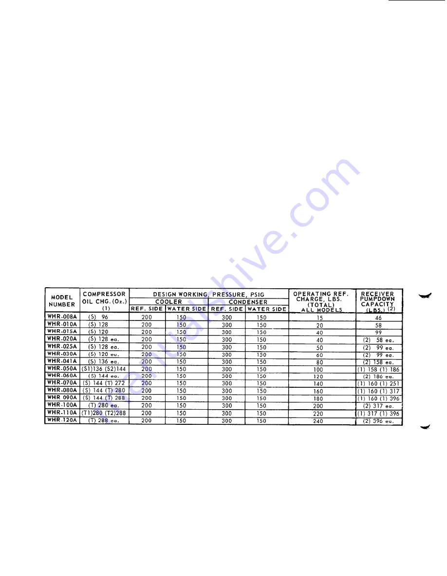
TABLE NO. 9 P H Y S I C A L D A T A
1) COMPRESSOR STYLE: S = SINGLE: T = TANDEM: S1 OR T1 I S L E S S E R H O R S E P O W E R O F T W O C O M P R E S S O R S . .
2) 80% FULL R-22 @100 F.
not
C O N T R O L C E N T E R E L E C T R I C A L S E R V I C E
The electrical control center is relatively easy to ser-
spot can be isolated to a particular section of the
vice. First, ascertain that the problem is actually
somewhere in the control panel. By referring to the
panel. From this point, it is a simple matter to find
and correct the malfunction. A service chart is pro-
schematic wiring diagrams, Diagrams 1 thru 6, Pages
14 thru21 and the Service Chart, Figure 19, the trouble
vided with each Seasonpak when shipped from the fac-
tory.
Page 26


