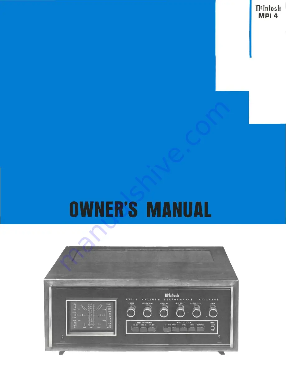
THE MclNTOSH MPI 4 MAXIMUM PERFORMANCE INDICATOR
R e a d i n g Time 40 Minutes
Price $1.25
Page 1: ...THE MclNTOSH MPI 4 MAXIMUM PERFORMANCE INDICATOR Reading Time 40 Minutes Price 1 25 ...
Page 2: ......
Page 3: ... the original performance limits free of any charge The SERVICE CONTRACT does not cover any shipping costs to and from the authorized service agency or the factory 2 Any Mclntosh authorized service agency will repair all Mc lntosh instruments at normal service rates To receive the free service under the terms of the SERVICE CONTRACT the SERVICE CONTRACT CERTIFICATE must accompany the in strument w...
Page 4: ...e two PANLOC buttons on the front panel of the MPI 4 releases the unit to slide in or out of its mounting This allows easy access to cable connections at the rear It brings top panel controls into view for easy adjustments adjustments Ventilation extends the trouble free life of an instru ment by preventing excessive internal temperature and insulation breakdown To accomplish this allow cool air t...
Page 5: ... cabinet How to connect The MPI 4 may be connected to a stereo receiver Fig 1 or to a component system with a separate preampli fier and power amplifier Fig 2 Choose which most closely resembles your system AUDIO INPUTS Low Level Audio Input Use one of the 6 foot shielded cables supplied to con nect the left channel output on your preamplifier to the LEFT AUDIO INPUT on the MPI 4 back panel Simila...
Page 6: ...HOW to Connect FIG 1 CONNECTING THE MPI 4 TO STEREO RECEIVER T Y P I C A L C O N N E C T I O N S STEREO RECEIVER AC CORD ENVIRONMENTAL EQUALIZER IF USED BLACK GREEN RED WHITE 4 ...
Page 7: ...FIG 2 CONNECTING MPI 4 TO COMPONENT SYSTEM TYPICAL CONNECTIONS STEREO FM TUNER LEFT SPEAKER 5 RIGHT SPEAKER E N V I R O N MENTAL EQUALIZER O P T I O N A L ...
Page 8: ... is often heard in the program signal 3 Stereo separation may be reduced 4 The stereo effect may be completely lost 5 Stereo indicators may fail to function or function erratically To overcome multipart reception it is usually necessary to turn the antenna to receive the FM signal by one pre dominant path Rotating a directional antenna is effective at correcting multipath reception In areas where ...
Page 9: ...control operates only when preamplifier signals are being displayed The GAIN control varies the vertical size of the image in all audio modes of operation When a signal of unknown strength is to be viewed start with the GAIN fully counterclockwise then turn the con trol until the display reaches comfortable viewing size When the GAIN control is set to OFF AC power is removed from the MPI 4 POWER L...
Page 10: ... used with most tuners TRACE SEPARATION The TRACE SEPARATION control adjusts the distance between the two traces in the DUAL TRACE mode of operation SWEEP EXPANSION The SWEEP EXPANSION control adjusts maximum width of the trace display SWEEP EXPANSION operates only when one or both of the DUAL TRACE pushbuttons are pressed TRIGGER SOURCE The TRIGGER SOURCE switch selects the signal used to trigger...
Page 11: ...he LEFT AUDIO OUTPUT ack is directly connected to the LEFT AUDIO INPUT jack of the MPI 4 Use the LEFT AUDIO OUTPUT jack to connect the preamplifier output to the left power amplifier input PREAMP RIGHT AUDIO OUTPUT The RIGHT AUDIO OUTPUT jack is directly connected to the RIGHT AUDIO INPUT jack of the MPI 4 Use the RIGHT AUDIO OUTPUT jack to connect the preamplifier output to the right power amplif...
Page 12: ...anel SWEEP control to the approxi mate midpoint of its range 14 Adjust the top panel SWEEP EXPANSION control to obtain the pattern shown in Figure 10 The control should position near the 1 marking 15 Depress the front panel R button Determine that the pattern is similar to that obtained in Fig 10 16 Depress both front panel L and R buttons 17 Adjust top panel TRACE SEPARATION to obtain the pattern...
Page 13: ... but is in addition an accurate tuning indicator Adjust the FM tuning dial until the trace reaches its highest point while also being centered horizontally on the screen Centering the trace places the signal at the center of the tuner s IF response curve the most desirable point An example of a detuned station is shown in Fig 15 note how the curve is shifted to the left on the screen Correct the t...
Page 14: ...roperly centered Steps 1 2 and 3 on pages 11 12 Then 1 Depress the STEREO pushbutton 2 Set the preamplifier or other program source to deliver a mono signal 3 Adjust the GAIN control to obtain approximately a 2 inch display 4 Balance the program source by making the trace on the screen fall precisely along the L R line This is done by adjusting the left and right gain or balance controls on the pr...
Page 15: ...rection and approximates a circle it is indicating excellent stereo separation between chan nels An example is shown in Fig 23 FIG 23 STEREO DISPLAY If the pattern tends toward an elliptical shape as in Fig 24 stereo separation is less than optimum FIG 24 REDUCED SEPARATION A pattern which tilts toward the left as in Fig 25 not only suggests reduced stereo separation but indicates an out of phase ...
Page 16: ...a sine wave a continuous tone the NORMAL and the PEAK will give the same dB reading The RESET position of the LEVEL mode switch quickly discharges the average Peak timing circuit for making another average Peak measurement In some instances it is desirable to stop the action and observe the highest point achieved by the audio signal over a period of time This permits close compari son between the ...
Page 17: ...HONO PICKUP COMPLIANCE AND TRACKING CHECK With the aid of a test record compliance and tracking of a pickup may be checked Follow the instructions on the test record jacket and make certain the spot on the MPI 4 is properly centered then 1 Depress the STEREO button 2 Start the phono turntable and set the pickup on the appropriate test band 3 Ad ust the GAIN control to obtain approximately a 2 inch...
Page 18: ...switch adds 5 dB 20 dB is generally considered fair 30 dB good and 40 dB excellent Repeat steps 2 3 and 4 but play the right channel for right to left channel separation measurements FIG 32 CHANNEL SEPARATION Approx 15dB AMPLIFIER LINEARITY CHECK With the aid of a test record you may perform an ampli fier linearity check Make this test and all single frequency tests at low acoustic levels to preve...
Page 19: ...IDEAL RIAA SYSTEM RESPONSE USING CBS STR 100 TEST RECORD FREQUENCY IN Hz FIG 33 17 20 I 00 1 000 10 000 20 000 20 18 16 14 12 10 8 6 4 2 0 2 4 4 2 0 2 4 6 8 10 12 14 16 18 20 20 000 10 000 1 000 100 20 ...
Page 20: ...s for lull scale indication 3dB in 9 calibrated steps Frequency Response 5Hz to 100kHz 3dB Input Impedance 75 000 W Calibration For bridging 4 8 or 16 ohm speaker loads PREAMP LEVEL MODE OF OPERATION Sensitivity 15mV rms for 3dB indication Frequency Response 5Hz to 50kHz Input Impedance 250 000 W SWEEP MODE OF OPERATION Display modes Left right or both dual trace Sensitivity 1 6mV rms cm 4 5mV P P...
Page 21: ...g is inserted into the front panel jack the preamplifier connections at the rear of the MPI 4 are disconnected and the front panel jack signals are displayed instead By setting the POWER LEVEL switch to a position other than PREAMP power amplifier signals are displayed SIGNAL PROCESSING Preamplifier signals and front panel signals are applied through LEFT and RIGHT AUDIO TRIM controls the GAIN con...
Page 22: ...paci tor value is selected by SWEEP FREQUENCY push buttons The high value resistor and high voltage effectively serve as a current source The linear ramp is fed into an emitter follower which provides the time base output and also drives a differential pair The amplitude of the time base output is controlled by the SWEEP EXPANSION The differential pair senses when the ramp has reached a certain vo...
Page 23: ...Block Diagram ...
Page 24: ...MclNTOSH LABORATORY INC 2 CHAMBERS ST BINGHAMTON N Y 13903 607 723 3512 Design subject to change without notice Printed in U S A 038 439 ...