BESPOKE RANGE OF
UNVENTED HOT WATER CYLINDERS
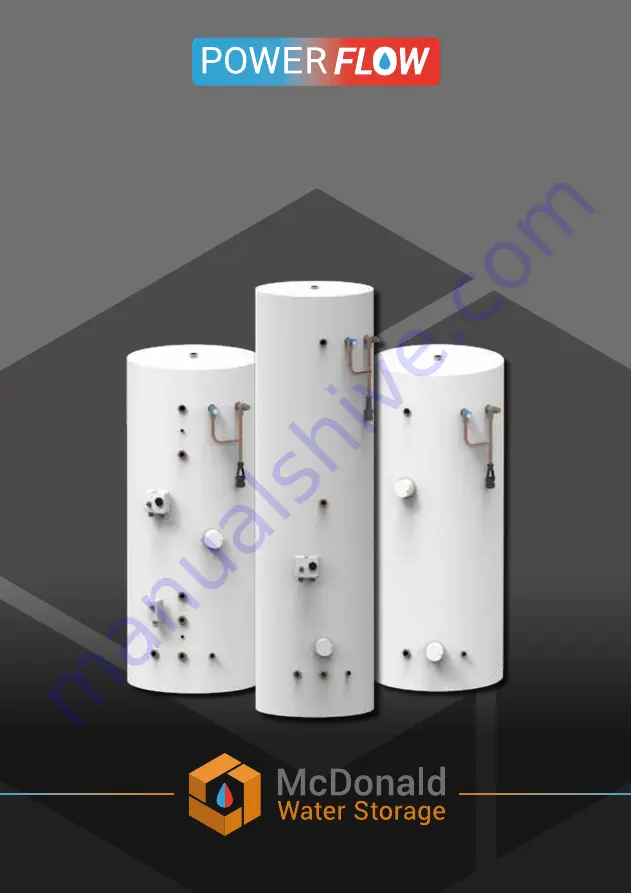
Installation & Service Instructions
Hot Water Storage Solutions
Page 1: ...BESPOKE RANGE OF UNVENTED HOT WATER CYLINDERS Installation Service Instructions Hot Water Storage Solutions ...
Page 2: ...Boiler and Soalr Connection 11 Electric Immersion Heaters and Connections 12 Discharge Pipe Arrangement 13 Wiring Diagram Two 2 Port Valves S Plan 16 Wiring Diagram 3 Port Mid Position Valve Y Plan 16 COMMISSIONING Filling the Cylinder 17 Storage Temperature 17 Safety Valve Checks 17 SERVICING AND MAINTENANCE Service The POWERflow Range 18 How to Drain the Cylinder 18 Annual Inspection Maintenance...
Page 3: ...rage products are manufactured under a ISO9001 2015 Quality Management System The POWERflow unvented cylinder must be installed and maintained by a competent person as defined by the relevant regulations IMPORTANT Please ensure that these instructions are left with the householder Failure to install and maintain this system in accordance with these instructions will invalidate the manufacturers wa...
Page 4: ...ures supplied please see below Operating pressure of the cylinder 1 5 bar 3 bar Max inlet pressure to pressure reducing valve 12 bar 12 bar Operating pressure PRV setting 1 5 bar 3 bar Expansion vessel charge pressure 1 5 bar 3 bar Expansion relief valve setting 3 bar 5 bar Opening pressure of P T Relief Valve 4 5 bar 7 bar All cylinders are manufactured in accordance with the requirements of BS E...
Page 5: ...upplied with the unvented cylinder DESIGN COMPONENT Direct Indirect Direct Solar Indirect Solar Pressure Reducing Valve Temperature and Pressure Relief Valve Fitted Expansion Relief Valve Fitted Tundish Fitted Check Valve 3kW Immersion Heater Primary Heat Source Fitted 3kW Immersion Heater Back Up Heat Source Fitted Expansion Vessel Dual Control and Overheat Thermostat Overheat Thermostat Two Port...
Page 6: ...e increased in size POSITIONING THE CYLINDER The POWERflow range must be installed vertically on a stable base which must be capable of supporting the weight when the cylinder is full of water The minimum recommended installation space is dependant on the specification of the cylinder Additional considerations should be made to allow space to mount the primary and secondary expansion vessels Full ...
Page 7: ...ontrol E Expansion Relief Valve F Tundish G Immersion Heater H Boiler Coil Flow I Boiler Coil Return J Solar Coil Flow K Solar Coil Return L Solar High Limit Thermostat M Cold Feed N Drain O Solar Probe Pocket Selected models only A A A A B B B B C C C C F F F F H I N N N J J K K N G G D G M M M L G L D O O I G M E E E O O G H E ...
Page 8: ...sure Loss Across Solar Coil bar 0 15 0 15 0 15 0 15 0 15 0 2 0 2 Dedicated Solar Volume 31 50 62 75 87 104 125 Heat Up Time 15 600C mins Primary heat source only 79 126 157 189 220 262 314 Immersion Heater 3KW Single Phase 230V 50hz Cylinder Material Copper Insulation Type White Cased Polyurethane PU insulation with CO2 Blowing Agent Insulation Thickness mm 50 50 50 50 50 50 50 Model Size 75 120 1...
Page 9: ...r Coil kW 12 19 24 28 33 39 47 Surface Area Of Solar Coil m2 1 0 1 2 1 2 1 2 1 2 1 5 1 5 Pressure Loss Across Solar Coil bar 0 15 0 15 0 15 0 15 0 15 0 2 0 2 Dedicated Solar Volume 31 50 62 75 87 104 125 Heat Up Time 15 600C mins Primary heat source only 20 20 20 20 20 20 20 Immersion Heater 3KW Single Phase 230V 50hz Cylinder Material Copper Insulation Type White Cased Polyurethane PU insulation ...
Page 10: ...k valve and cylinder to provide a balanced cold outlet for all cold taps preventing cross flow and also providing potable water throughout the property Outdoor taps for hoses should be taken before the pressure reducing valve The check valve is supplied loose to be fitted between the pressure reducing valve and before the expansion vessel on the cold feed Any balanced cold draw off should be fitte...
Page 11: ... should be connected to the tee No isolating valve is permitted between the expansion vessel and cold feed SECONDARY RETURN CIRCULATION Allmodels180litresandabovearefittedwithasecondaryreturntappingasstandard Where a secondary circulation loop is greater than 15 of the unit capacity an extra expansion vessel may be required to ensure expansion of the additional volume is absorbed A non return valv...
Page 12: ...dual thermostat controller supplied with the indirect units should be set to no greater than 600C and the internal high limit thermostats are factory set no higher than 800C All electrical wiring to thermostats zone valves and immersion heaters must be earthed and to current IEE Wiring Regulations The fuse should generally be 3 Amps but refer to component instructions to confirm this All wiring sh...
Page 13: ...as the unvented hot water storage system and be fitted as close as possible to and lower than the safety device with no more than 600mm of pipe between the valve outlet and the tundish Any Discharge should be visible at the tundish The tundish should be located such that any discharge is visible In addition where discharges from safety devices may not be apparent e g people with impaired vision or...
Page 14: ... the nominal outlet size of the safety device between 18 and 27m at least 3 sizes larger and so on Bends must be taken into account in calculating the flow resistance Refer to diagram 1 Table 1 and the worked example An alternative approach for sizing discharge pipes would be to follow BS6700 Specification for design installation testing and maintenance of services supplying water for domestic use...
Page 15: ... to 5 8m 5 8m is less than the actual length of 7m therefore calculate the next largest size Maximum resistance allowed for a straight length of 28mm pipe D2 from a G1 2 temperature relief valve equates to 14m As the actual length is 7m a 28mm D2 copper pipe will be satisfactory INSTALLATION Sizing of copper discharge pipe D2 for a temperature relief valve with a G1 2 outlet size as supplied Size ...
Page 16: ...5A SUPPLY KEY Bl Blue Br Brown C Common Terminal E Earth G Grey G Y Green Yellow L Live N Neutral O Orange SL Switched Live W White Note The programmer and boiler power can be taken either from the Wiring Centre or from elsewhere as appropriate E E E 3 PORT Mid Position HIGH LIMIT CUTOUT CONTROL STAT 2 PORT DHW W G Bl C E E 1 1 2 C G Br Bl 0 2 1 2 0 10 WAY WIRING CENTRE 1 2 L N 3 4 5 6 7 8 9 10 1 ...
Page 17: ... thermostats are set no higher than 850C The use of excessive flux should be avoided When soldering above the cylinder ensure flux solder does not contaminate the cylinder below since this can cause corrosion STORAGE TEMPERATURE The recommended storage temperature for a POWERflow cylinder is 60 650C Considerations should be made for the prevention of legionella control For details please consult t...
Page 18: ... MAINTENANCE The POWERflow range requires an annual service to ensure continued safe operation and optimum efficiencies It is essential that the following tasks are carried out by a qualified engineer on an annual basis Turn the cap of the expansion relief valve Water should be allowed to flow for at least 5 seconds Upon release make sure it re seats fully Carry out the same procedure with the pre...
Page 19: ... being discharged as the water is heated this would indicate that the expansion vessel needs recharging Switch off all power to the cylinder and recharge vessel as below If water is continually being discharged firstly check with a gauge that the pressure allowed through the pressure reducing valve does not exceed 2 1 bar see page 4 for other model settings If it does remove filter and clean Next ...
Page 20: ... accumulation of lime scale To comply with this requirement the hardness of the mains water should be checked by the installer and if necessary the optional factory fitted in line scale inhibitor should be specified at the time of order for hardness levels between 200 and 300 ppm mg l Where the water is very hard ie 300ppm mg l and above the optional polyphosphate type inhibitor should be specifie...
Page 21: ...re Reducing Valve 1 5 bar WUVPRC 5 22mm Check Valve WUVC 6 15mm Expansion Relief Valve 3 bar WUVER3 7 15mm Expansion Relief Valve 3 5 bar WUVER 8 15mm Expansion Relief Valve 5 bar WUVER5 9 15mm T P Valve 4 5 bar WUVTP 10 15mm T P Valve 7 bar WUVTP7 11 12 litre expansion vessel WU12EV 12 18 litre expansion vessel WU18EV 13 25 litre expansion vessel WU25EV 14 35 litre expansion vessel WU35EV 15 22mm...
Page 22: ...e of installation and is not fed with water from a private supply Particular Chloride content Max 200mg l Sulphate content Max 200mg l Combination chloride sulphate Max 300mg l in total It has not been subject to wrong or improper use left uncared for or subjected to scale or frost damage In accordance with the Building Regulations L1A New Dwellings L1B Existing Dwellings the requirements set out ...
Page 23: ...the conditions of use of the goods or the time or manner or location in which they will be installed and the purchaser agrees to be fully responsible for testing and checking all works which include the goods at all relevant times up to including and after commissioning and for taking all necessary steps to identify any leaks and prevent any damage being caused thereby All components fitted to or ...
Page 24: ...PRIMARY SETTINGS indirect heating only Is the primary circuit a sealed or open vented system Sealed Open What is the maximum primary flow temperature C ALL SYSTEMS What is the incoming static cold water pressure at the inlet to the system bar Has a strainer been cleaned of installation debris if fitted Yes No Is the installation in a hard water area above 200ppm Yes No If yes has a water scale red...
Page 25: ...either directly or through a Competent Persons Scheme A Building Regulations Compliance Certificate will then be issued to the customer Heating and Hotwater Industry Council HHIC www centralheating co uk Where is the pressure reducing valve situated if fitted What is the pressure reducing valve setting bar Has a combined temperature and pressure relief valve and expansion valve been fitted and dis...
Page 26: ...rer s instructions SERVICE RECORD SERVICE 01 Date Engineer name Company name Telephone No Comments Signature SERVICE 03 Date Engineer name Company name Telephone No Comments Signature SERVICE 05 Date Engineer name Company name Telephone No Comments SERVICE 02 Date Engineer name Company name Telephone No Comments Signature SERVICE 04 Date Engineer name Company name Telephone No Comments Signature S...
Page 27: ...CE 09 Date Engineer name Company name Telephone No Comments Signature Signature SERVICE 06 Date Engineer name Company name Telephone No Comments Signature SERVICE 08 Date Engineer name Company name Telephone No Comments Signature SERVICE 10 Date Engineer name Company name Telephone No Comments Signature SERVICE RECORD Attach additional paperwork for all subsequent services ...
Page 28: ...QUEENSWAY INDUSTRIAL ESTATE GLENROTHES FIFE KY7 5QF T 01592 611123 F 01592 611166 E sales mcdonaldwaterstorage com www mcdonaldwaterstorage com 1945 2020 ...