McCrometer FlowConnect FC500 Instructions Manual Download Page 10

30122-37  Rev. 1.1 | 06APR2022

Page 10

FlowConnect FC500 Retrofit Instructions

FlowConnect

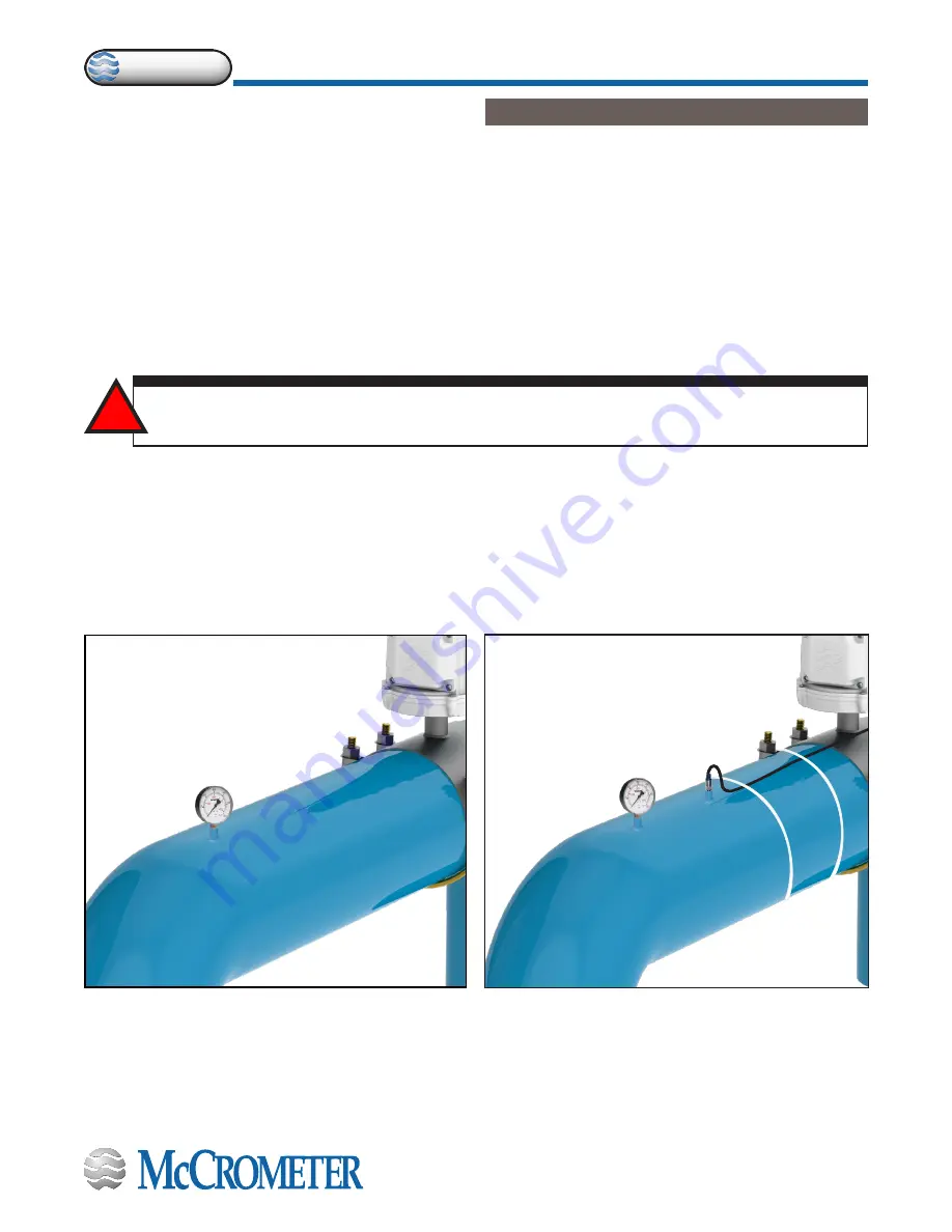
4:   Installing a pressure sensor

If you want to install a pressure sensor that can transmit 

measurement data to the FlowConnect  unit, you will need 

the tools and materials listed at right.

This instruction is for a pipe that has an existing pressure 

gauge. If your pipe does not already have a location 

tapped and threaded, that will need to be done first. When 

completed, follow this instruction from step 2 below.

a.  Remove the existing gauge from the pipe.

b.  Clean the interior pipe threads and remove any debris.

c.  Wrap the pipe threads on the pressure sensor with 

Teflon tape.

!

WARNING!

Never remove a gauge while the line is under pressure!

d.  Screw in the pressure sensor by hand until it is tight, 

then use the channel locks to fully tighten it.

e.  Connect the extension cable to the pressure sensor. 

f.  Coil and secure any extra sensor cable with zip ties to 

prevent cable from being damaged or becoming a 

hazard.

TOOLS AND MATERIALS

Note: Sensor parts are sold individually or as a bundle. 

The parts listed below are for sensor and cable bundles.

PA-1 sensor and 10 m cable bundle (500.000.119) or
PA-1 sensor and 5 m cable bundle (500.000.120)
Cable for PA-1 pressure sensor
PA-1 pressure sensor 0-30 bar (200.733.162)
Crescent wrench or adjustable wrench
Channel locks (need to accommodate 3/4” pressure gauge)
Brass or steel wire brush

Summary of Contents for FlowConnect FC500

Page 1: ...7 Attach the FlowConnect unit at the remote mount location STEP 8 Attach the antenna STEP 9 Connect the batteries and attach the battery cover STEP 10 Attach the tamper evident seals 2 Installing Sen...

Page 2: ...Standard flat head screwdriver Precision flat head screwdriver Part Number Description Quantity Part Number Description Quantity 30122 20 IOM Manual 1 TOB008 WS Base Plate 1 TOB018 O Ring for Base Pl...

Page 3: ...will need to replace the sensor cable from the meter head If you plan to install sensors or a solar panel plan their location at the same time You may choose to do STEP 3 through STEP 6 in the order y...

Page 4: ...f STEP 5 Replace the submergible remote mount kit at the meter head NOTE You will replace most of parts referred to in this step using the submergible remote mount kit a Guide the cable through the pi...

Page 5: ...s from the strain reliefs in the FlowCom base plate a x4 STEP 6 Remove the FlowCom unit WARNING Do not proceed with step 6 until you are certain the power has been shut off STEP 7 Attach the FlowConne...

Page 6: ...tteries a Remove the battery cover b Ensurethebatteriesareinplaceand plug the leads into the connectors in the order shown in Figure 5 and Figure 6 STEP 9 Connect the batteries and attach the battery...

Page 7: ...hed through the hole in the security screw and a small hole in the chassis next to the security screw a Thread the wire end through the security hole in the screw and through the hole in the chassis n...

Page 8: ...ge or antenna extension We recommend installing the mast plumb The lower part ofthemastmaybeburiedorcementedintotheground or it may be secured to surrounding fixed objects The installation should be s...

Page 9: ...g a rain gauge Tools and Materials Rain Gauge kit model RG1 7 mm socket driver 7 pin male to female extension cable Use a 7 mm socket driver and two hose clamps to secure the rain gauge to the top of...

Page 10: ...ap the pipe threads on the pressure sensor with Teflon tape WARNING Never remove a gauge while the line is under pressure d Screw in the pressure sensor by hand until it is tight then use the channel...

Page 11: ...only ONE sensor can be connected at a remote mount No more than TWO inputs can be connected to the FlowConnect using a Y connector SCADA UNIT SCADA UNIT Cable from solar panel connects to POWER termi...

Page 12: ...the Inputs port To connect more than one sensor to the Inputs port a Y Cable 200 720 510 is needed No more than two sensors can be connected at once so only one Y Cable is required 3 Outputs connecto...

Page 13: ...f the values until you come to the selection you want Time out the programming mode If you can t find the value you want or find the menu you need allow the programming mode to time itself out This is...

Page 14: ...DE P P b Pass the wand on the three times The second digit from the left will flash Figure 16 c Pass the wand on the once The display will increment from 0 to 1 Figure 16 A lock code of 01000 is requi...

Page 15: ...ot dP Totalizer Decimal Place Sets Decimal Place Tot FAct Totalizer Multiplier Sets Multiplier 20mA Un 20mA Unit Sets 20mA Unit 20mA dP 20mA DP Sets 20mA Decimal Place 20mA FS 20mA FS 20mA Full Scale...

Page 16: ...sts 4mA Zero 20mA AdJ Trim 20mA Adjusts 20mA FS PLS tYPE Pulse Type Sets Pulse Type PLSwidth Pulse Width Sets Pulse Width in ms RESEttot Reset Total Zeroes Total DIS rSt Disable Reset Total Permanent...

Page 17: ...rent pricing technical data and instructions Page 17 P P P NOTE At the L2 Go To selection if you pass the wand over P to move to the second menu level the selection rUn Go to will appear Then if you m...

Reviews: