- 7 -
SERVICE
Assembly and disassembly should be performed by a
service technician who has been factory trained on MBW
equipment. The unit should be clean and free of debris.
Pressure washing before disassembly is recommended.
• Prior to assembly, wash all parts in a suitable cleaner or
solvent.
• Check moving parts for wear and failure. Refer to the
Replacement section in this manual for tolerance and
replacement cycles.
• All seals and bearings should be oiled prior to assembly.
Also, ensure that the seals are inserted square and are
seated properly.
• Leaking air caused by worn seals will decrease
performance of Ergo-Tamp.
General
The disassembly and assembly procedures given here are
intended for a complete dismantling of the MBW Ergo-
Tamp. Read the following sections carefully.
Handle and Tamper Separation
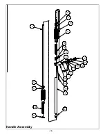
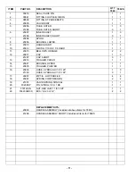
Refer to Handle Assembly, page 10.
1.
Remove the bottom zip tie (#17) from the bellows
(#11)
2.
Loosen jam nut (#21) from tamper cap and unscrew
Tamper Assembly from Handle Assembly.
Handle Disassembly
Refer to Handle Assembly, page 10.
3.
Detach the hose (#16) from cap (#12) and fitting (#3).
4.
Remove the zip ties (#17) from both bellows (#11).
5.
Unscrew the jam nut (#21) from the handle.
6.
Slide inner shaft (#6) up out of outer tube (#5).
7.
Slide bellows (#11) and springs (#18) off.
8.
Remove coupler (#2) from valve body. Don’t loose
the spring (#19)
9.
Remove the two screws (#22) from the hand guard
(#9) and slide guard off of handle.
10. Unthread lower and upper bushing (#8, #14). (Note:
Due to thread locking compound used in assembly
heat might be need to help loosen bushings.)
11. Slide valve body assembly (#4) off of outer tube (#5).
12. Using a 10-32 bolt, pull the spool (#7) out of the valve
body (#4), then separate the o-ring (#10) and valve
seal (#1).
Handle Assembly
Refer to Handle Assembly, page 10.
1.
Lubricate new o-ring (#10) with air tool oil and then
place on spool (#7).
2.
Lubricate valve seal (#1) and spool (#7) and insert in
valve body (#4).
3.
Slide valve body (#4) onto outer tube (#5).
4.
Using medium-strength thread locking compound,
screw lower bushing (#8) and upper bushing (#14)
(through valve body (#4)) to outer tube (#5).
5.
Slide hand guard (#9) into position and secure with
the two bolts (#22).
6.
Insert conical spring (#19), narrow end first, into valve
body, then screw coupler (#2) in. Use pipe sealing
compound on threads of coupler.
7.
Grease inner shaft (#6) and slide into outer tube (#5).
The end with the longer threads needs to be towards
the bottom of the handle.
8.
Slide the springs (#18) onto the inner shaft (#6) and
then cover springs with bellows (#11).
9.
Secure top spring (#18) with cap (#12) and bottom
spring (#18) with jam nut (#21).
10. Seat two zip ties (#17) to both bellows (#11). (Note:
Position zip ties to fit into grooves of parts ).
11. Attach hose (#16) to fitting (#3) and cap (#12).
Tamper Disassembly
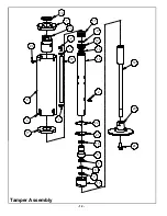
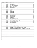
Refer to Tamper Assembly, page 12.
1.
Remove bolt (#24) and tap the tamper foot (#23) off
from shaft (#14).
2.
Remove retaining ring (#22), lift locking ring (#21)
and remove cap (#15).
3.
Remove shim (#5) and wiper (#3) from bottom cap
(#15).
4.
Slide bushing support (#8) out of body (#10) and
remove seal set (#4) and o-ring (#16).
5.
Grasp shaft (#14) and remove from body (#10).
6.
Take out the four screws (#20) from the top shroud
cover (#7).
7.
While holding the outer shroud (#6) push the body
(#10) into the shroud.
Summary of Contents for ERGO-TAMP
Page 13: ...10 Handle Assembly...
Page 15: ...12 Tamper Assembly...


