background image

BIO Assembly Instructions 


Page 

5

 of 

14


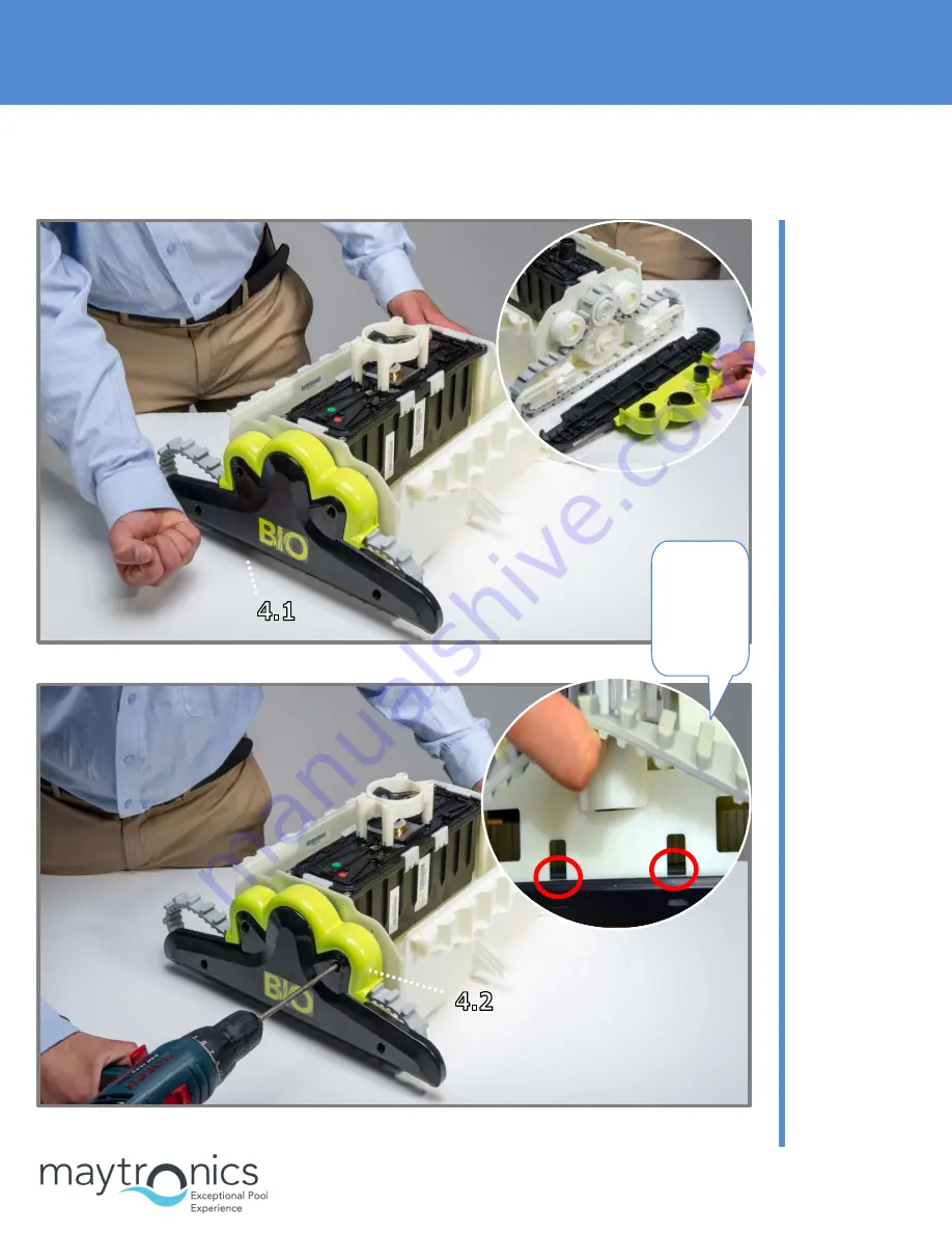
4. Assembling the Side Panels 


Step 4.1 

Put the side 
panels into place 
on both sides of 
the robot. 


Step 4.2 

Secure the side 
panels in place 
with 4 KA50X20 
screws on both 
sides of the robot. 


Note:


Make 
sure the 
clips are 
in place.  


Summary of Contents for BIO

Page 1: ...iving System 3 4 Assembling the Side Panels 5 5 Assembling the Floating Cable 6 6 Positioning the Floats 7 7 Positioning the Brush Covers 8 8 Assembling the Outer Casing 8 9 Assembling the Impeller Cover 9 01 Assembling the Cartridge Door 10 11 Assembling the Handle 11 12 Assembling the Suction Inlet Plug 12 13 Assembling the Brushes 13 ...

Page 2: ...BIO Assembly Instructions Page 2 of 14 1 Assembling the Diaphragms 2 Assembling the Motor Unit Step 1 1 Insert two diaphragms Step 2 1 There is only one way to place the motor unit in the frame ...

Page 3: ...BIO Assembly Instructions Page 3 of 14 3 Assembling the Driving System Step 2 2 Secure the motor unit to the frame with 4X KA50X20 screws Step 3 1 Place 4 guide wheels on both sides of the robot ...

Page 4: ...exagon adaptors into the pulley Step 3 3 Put the pulley and the Active Brush gear in their places on both sides of the robot Step 3 4 Place the track in its place as shown on both sides of the robot Step 3 5 Place the side floats on both sides of the robot ...

Page 5: ... 5 of 14 4 Assembling the Side Panels Step 4 1 Put the side panels into place on both sides of the robot Step 4 2 Secure the side panels in place with 4 KA50X20 screws on both sides of the robot Note Make sure the clips are in place ...

Page 6: ...able Step 5 1 Connect the cable s retrofit to motor unit mind the slot shape and press it firmly Step 5 2 Press the seal firmly to the terminal Step 5 3 Tighten the nut properly by hand Note There is only one way for the connector to connect to the motor unit terminal ...

Page 7: ... 7 of 14 6 Positioning the Floats Step 5 4 Position the floating cable on the motor unit and secure the cable holders with 4 50X12 screws Step 5 5 The cable position on the motor unit Step 6 1 Place the two floats on the motor unit ...

Page 8: ...embling the Outer Casing Step 7 1 Position the 2 brush safety covers on both sides of the robot Step 7 1 Position the 2 brush safety covers on both sides of the robot Step 8 1 Place the outer casing on the frame Step 8 2 Secure the outer casing to the frame with 4 50X20 screws ...

Page 9: ...mbling the Impeller Cover Step 9 1 Place the cable support in its place on the outer casing before closing the impeller cover Step 9 2 Position the impeller cover diagonally on the outer casing Step 9 3 Secure the impeller cover with a 50X12 screw ...

Page 10: ...01 Assembling the Cartridge Door Step 10 1 Place the cartridge door on the casing Place the top side first on both sides of the robot Step 10 2 Press strongly on the bottom of the door to fit the clips into place Tip Place the top side first ...

Page 11: ...BIO Assembly Instructions Page 11 of 14 11 Assembling the Handle Step 11 1 Position the handle Step 11 2 Secure the handle in place with 2 50X20 screws Note The handle s position ...

Page 12: ...BIO Assembly Instructions Page 12 of 14 12 Assembling the Suction Inlet Plug Step 12 1 Place the inlet on the side of the hose connection Step 12 2 Assemble the inlet Note The hose connection side ...

Page 13: ...Assembly Instructions Page 13 of 14 13 Assembling the Brushes Step 13 1 Place the Active Brush in its place Step 13 2 Secure the Active Brush in place with 4 50X20 screws Step 13 3 Place one brush in place ...

Page 14: ...BIO Assembly Instructions Page 14 of 14 Step 13 4 Place the second brush in its place by pulling it strongly against you Tip Using a screwdriver makes it easier to insert the brush in place ...

Page 15: ...rtridge Door 3 3 Dismantling the Impeller Cover 4 4 Dismantling the Outer Casing 5 5 Dismantling the Cable 6 6 Dismantling the Side Panels 7 7 Dismantling the Driving System 8 8 Dismantling the Motor Unit 9 9 Dismantling the Suction Inlet Plug 10 10 Dismantling the Brushes 10 11 Dismantling the Diaphragms 11 ...

Page 16: ...BIO Disassembly Instructions Page 2 of 11 1 Dismantling the Handle Step 1 1 Unscrew the 2 screws holding the handle in place Step 1 2 Take the handle off ...

Page 17: ...ly Instructions Page 3 of 11 2 Dismantling the Cartridge Door Step 2 1 Dismantle the cartridge door using a flat screwdriver as shown in the picture Step 2 2 Remove the cartridge doors from both sides of the Dolphin ...

Page 18: ...structions Page 4 of 11 3 Dismantling the Impeller Cover Step 2 3 Remove the suction sleeve Step 3 1 Unscrew the screw holding the impeller cover in place Step 3 2 Lift the impeller cover up from one side and take it off ...

Page 19: ...y Instructions Page 5 of 11 4 Dismantling the Outer Casing Step 4 1 Remove the black grommet Step 4 2 Unscrew the 4 screws holding the outer casing in place Step 4 3 Hold the outer casing on both sides and pull it up ...

Page 20: ...tructions Page 6 of 11 5 Dismantling the Cable Step 5 1 Remove 2 floats from the motor unit Step 5 2 Unscrew the 4 screws securing the cable holder Step 5 3 Unscrew the cable from the motor unit Step 5 4 Unplug the cable ...

Page 21: ...BIO Disassembly Instructions Page 7 of 11 6 Dismantling the Side Panels Step 6 1 Unscrew the 4 screws holding each panel in place Step 6 2 Pull the side panels off ...

Page 22: ...iving System Step 7 1 Remove the pulley together with the track from both sides of the robot Step 7 2 Remove the guide wheels Step 7 3 Remove the Active Brush s driving wheel from both sides of the robot Step 7 4 Remove the side floats from both sides of the robot ...

Page 23: ...BIO Disassembly Instructions Page 9 of 11 8 Dismantling the Motor Unit Step 8 1 Unscrew the 4 screws securing the motor unit to the frame Step 8 2 Remove the motor unit ...

Page 24: ... Dismantling the Suction Inlet Plug 10 Dismantling the Brushes Step 9 1 Dismantle the inlet using a small and flat screwdriver Step 9 2 Remove the inlet Step 10 1 Remove the brushes Tip Using a flat screwdriver makes it easier to remove the brush ...

Page 25: ...BIO Disassembly Instructions Page 11 of 11 11 Dismantling the Diaphragms Step 10 2 Open the 4 screws holding the active brush in place Step 10 3 Remove the Active Brush Step 11 1 Remove the 2 diaphragms ...

Reviews: