background image

13

RANGE HOOD USE

The range hood is designed to remove smoke, cooking vapors 
and odors from the cooktop area. For best results, start the hood 
before cooking and allow it to operate several minutes after the 
cooking is complete to clear all smoke and odors from the 
kitchen.

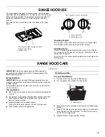
The hood controls are located on the front panel of the range 
hood.

Range Hood Controls

Operating the light

Turn the light switch to the right 1 position for Low (night light).

Turn the light switch to the right 2 positions for High.

Operating the fan

The fan is variable speed. Rotate the fan switch to the right to 
turn the fan to the ON position. Continue to rotate the switch to 
the desired fan speed.

To turn the fan OFF, rotate the fan speed switch to the left to the 
OFF position.

RANGE HOOD CARE

Cleaning

IMPORTANT: Clean the hood and grease filters frequently 
according to the following instructions. Replace grease filter 
before operating hood.

Exterior Surfaces:

IMPORTANT: Do not use soap-filled scouring pads, abrasive 
cleaners, Cooktop Polishing Creme, steel wool, gritty washcloths 
or paper towels.

To avoid damage to the stainless steel, do not use cleaners that 
contain chlorine.

Cleaning Method:

Rub in direction of grain to avoid scratching or damaging the 
surface.

For stainless steal models, Stainless Steel Cleaner and Polish 
Part Number 31462A (not included): See “Assistance or 
Service” section to order.

Liquid detergent or all-purpose cleaner:
Rinse with clean water and dry with soft, lint-free cloth.

Glass cleaner to remove fingerprints.

Metal Grease Filter

For vented installations:

1. Remove screw from the grease filter retainer.

2. Turn the grease filter retainer to release filter. 

3. Wash metal filters as needed in dishwasher or hot detergent 

solution.

4. Reinstall the filter by placing the back edge in the channel at 

rear of hood. Push filter into place, turn the filter retainer to 
secure filter to range hood.

5. Replace screw in the grease filter retainer.

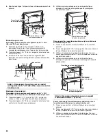
A. Incandescent light housing and cover
B. Grease filter retainer

C. Grease filter

A

C

B

A. Fan speed switch
B. On/Off light switch

A

B

A. Filter retainer

A

Summary of Contents for UXT4230AY

Page 1: ...lpool ca HOTTE D ASPIRATION DE 30 76 2 CM ET 36 91 4 CM Instructionsd installationetGuided utilisationetd entretien Au Canada pour assistance installation ou service composer le 1 800 807 6777 ou visiter notre site Web à www whirlpool ca Table of Contents Table des matières 2 IMPORTANT READ AND SAVE THESE INSTRUCTIONS FOR RESIDENTIAL USE ONLY IMPORTANT LIRE ET CONSERVER CES INSTRUCTIONS POUR UTILI...

Page 2: ...r l installation 28 UTILISATION DE LA HOTTE 28 Commandes de la hotte de cuisinière 28 ENTRETIEN DE LA HOTTE 29 Nettoyage 29 SCHÉMA DE CÂBLAGE 30 ASSISTANCE OU SERVICE 31 Au Canada 31 Accessoires 31 GARANTIE 31 RANGE HOOD SAFETY You can be killed or seriously injured if you don t immediately You can be killed or seriously injured if you don t follow All safety messages will tell you what the potent...

Page 3: ...ical wiring and other utilities Ducted fans must always be vented outdoors CAUTION For general ventilating use only Do not use to exhaust hazardous or explosive materials and vapors CAUTION To reduce risk of fire and to properly exhaust air be sure to duct air outside do not vent exhaust air into spaces within walls or ceilings attics or into crawl spaces or garages WARNING TO REDUCE THE RISK OF F...

Page 4: ... For information on ordering see the Accessories section LocationRequirements IMPORTANT Observe all governing codes and ordinances It is the installer s responsibility to comply with installation clearances specified on the model serial rating plate The model serial rating plate is located inside the range hood on the left wall Range hood location should be away from strong draft areas such as win...

Page 5: ...f the vent system The damper should be on the cold air side of the thermal break The break should be as close as possible to where the vent system enters the heated portion of the house Makeup Air Local building codes may require the use of makeup air systems when using ventilation systems greater than specified CFM of air movement The specified CFM varies from locale to locale Consult your HVAC p...

Page 6: ...8 cm 90 elbow 5 0 ft 1 5 m Maximum Recommended Length 50 ft 15 2 m 1 90 elbow 5 0 ft 1 5 m 1 wall cap 0 0 ft 0 0 m 8 ft 2 4 m straight 8 0 ft 2 4 m Length of 7 17 8 cm system 13 0 ft 3 9 m Wall cap 7 17 8 cm round 90 elbow 2 ft 0 6 m 6 ft 1 8 m Vent Piece 3 x 10 8 3 cm x 25 4 cm 90 elbow 5 0 ft 1 5 m 3 x 10 8 3 cm x 25 4 cm flat elbow 12 0 ft 3 7 m 3 x 10 8 3 cm x 25 4 cm wall cap 0 0 ft 0 0 m Max...

Page 7: ...g practices Wire sizes and connections must conform with the rating of the appliance as specified on the model serial rating plate The model serial plate is located behind the filter on the rear wall of the range hood Wire sizes must conform to the requirements of the National Electrical Code ANSI NFPA 70 latest edition or CSA Standards C22 1 94 Canadian Electrical Code Part 1 and C22 2 No 0 M91 l...

Page 8: ...9 8 cm down from underside of cabinet and mark on the centerline on the back wall 2 Mark lines 5 13 3 cm to the right and left of the centerline on the wall 3 Use saber or keyhole saw to cut a rectangular opening in the wall for the vent Style 2 Cut Openings for 3 x 10 8 3 x 25 4 cm Rectangular Vent to Round Vent Transition Roof Venting To make a 4 x 10 10 8 cm x 26 7 cm rectangular cutout on the ...

Page 9: ... Your model will have a 3 x 10 8 3 x 25 4 cm rectangular vent damper on the inside of the range hood 1 Remove the 3 x 10 8 3 x 25 4 cm rectangular vent damper attached with 3 5 x 9 5 mm screws on the inside your range hood Use these screws to install the rectangular vent damper 2 Lift the range hood up under cabinet and determine final location by centering beneath cabinet Mark on the underside of...

Page 10: ...round vent mounting plate and 3 x 10 8 3 x 25 4 cm rectangular vent damper can be installed up to 1 2 5 cm on either side of the hood center to accommodate off center ductwork If a vent damper is installed with a wall cap with damper check that they do not interfere with each other Remove the vent connector damper flap if they interfere Non vented recirculating installations No vent attachments Re...

Page 11: ...e only with range hood cord connection kits that have been investigated and found acceptable for use with this model range hood Do not reconnect power until the installation is complete 2 Remove the screw from the terminal box cover Remove terminal box cover and set aside 3 Remove the power supply knockout from the top or rear of the vent hood depending on the incoming location of your home power ...

Page 12: ...ction If range hood does not operate check to see whether a circuit breaker has tripped or a household fuse has blown Disconnect power and check wiring connections NOTE To get the most efficient use from your new range hood read the Range Hood Use section A White wires B Black wires C UL listed wire connector D Green or bare ground wire E Home power supply cable or power cord accessory kit F UL li...

Page 13: ...TANT Do not use soap filled scouring pads abrasive cleaners Cooktop Polishing Creme steel wool gritty washcloths or paper towels To avoid damage to the stainless steel do not use cleaners that contain chlorine Cleaning Method Rub in direction of grain to avoid scratching or damaging the surface For stainless steal models Stainless Steel Cleaner and Polish Part Number 31462A not included See Assist...

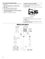
Page 14: ... off the range hood and allow the light bulb to cool 1 Disconnect power 2 Squeeze the plastic lens cover and remove it from the hood 3 Screw light bulb into socket 4 Replace lens cover by squeezing cover and inserting tabs into slots 5 Reconnect power If new light does not operate make sure the lamp is inserted correctly before calling service WIRING DIAGRAM A Light bulb socket B Lens cover A B L ...

Page 15: ...ome Appliances Customer eXperience Center 553 Benson Road Benton Harbor MI 49022 2692 Please include a daytime phone number in your correspondence InCanada Call the Whirlpool Canada LP Customer eXperience Centre toll free 1 800 807 6777 or visit our webpage www whirlpool ca Our consultants provide assistance with Scheduling of service Whirlpool designated service technicians are trained to fulfill...

Page 16: ...ble parts i e light bulbs batteries air or water filters preservation solutions etc 5 Conversion of products from natural gas or L P gas 6 Damage from accident misuse abuse fire floods acts of God or use with products not approved by Whirlpool 7 Repairs to parts or systems to correct product damage or defects caused by unauthorized service alteration or modification of the appliance 8 Cosmetic dam...

Page 17: ...areil ménager Assurez vous de toujours lire tous les messages de sécurité et de vous y conformer AVERTISSEMENT DANGER Voici le symbole d alerte de sécurité Ce symbole d alerte de sécurité vous signale les dangers potentiels de décès et de blessures graves à vous et à d autres Tous les messages de sécurité suivront le symbole d alerte de sécurité et le mot DANGER ou AVERTISSEMENT Ces mots signifien...

Page 18: ...die et évacuer adéquatement les gaz veiller à acheminer l air aspiré par un conduit jusqu à l extérieur ne pas décharger l air aspiré dans un espace vide du bâtiment comme une cavité murale un plafond un grenier un vide sanitaire ou un garage AVERTISSEMENT POUR RÉDUIRE LE RISQUE D INCENDIE UTILISER UNIQUEMENT DES CONDUITS MÉTALLIQUES AVERTISSEMENT POUR MINIMISER LE RISQUE D UN FEU DE GRAISSE SUR L...

Page 19: ... voir la section Accessoires Exigencesd emplacement IMPORTANT Observer les dispositions de tous les codes et règlements en vigueur C est à l installateur qu incombe la responsabilité de respecter les distances de séparation exigées spécifiées sur la plaque signalétique de l appareil La plaque signalétique est située à l intérieur de la hotte sur la paroi de gauche Installer la hotte de cuisinière ...

Page 20: ...MARQUE Si l on utilise un clapet anti reflux il est possible que la cuisinière ne réponde pas aux critères du document California Title 24 À l aide d un produit de calfeutrage assurer l étanchéité autour de la bouche de décharge à l extérieur à travers le mur ou le toit Installations dans les régions au climat froid On doit installer un clapet anti reflux supplémentaire à l arrière pour minimiser ...

Page 21: ... rond de dia 7 17 8 cm pour décharge à travers le toit achat séparé Conduit rectangulaire de 3 x 10 8 3 x 25 4 cm pour décharge à travers le toit achat séparé B Bouche de décharge sur toit avec clapet achat séparé C Entre 24 61 cm min au dessus de la surface de cuisson A Conduit rond de dia 7 17 8 cm avec sortie par le dessus et décharge à travers le mur achat séparé Conduit rectangulaire de 3 x 1...

Page 22: ...ection ajoutée de câblage en cuivre en utilisant des connecteurs et ou des outils spécialement conçus et homologués UL pour fixer le cuivre à l aluminium Suivre la procédure recommandée par le fabricant de connecteurs électriques Les raccordements aluminium cuivre doivent satisfaire aux prescriptions des codes locaux et de l industrie et être conformes aux pratiques de câblage reconnues Le calibre...

Page 23: ...e distance A à partir de la droite de l axe central sur la face inférieure du placard Sur cette ligne marquer le point situé à 2 5 1 cm du mur arrière Percer en ce point un trou de 1 3 2 cm de diamètre à travers le placard Passage du câble à travers le mur 1 Tracer une ligne de distance A à partir de la droite de l axe central sur la face inférieure du mur Marquer un point sur cette ligne qui se t...

Page 24: ...sur la face inférieure du sommet du placard 1 Tracer un axe central sur la face inférieure du sommet du placard 2 Tracer une ligne de 5 12 7 cm en partant du mur arrière sur la face inférieure du sommet du placard 3 Utiliser un compas ou un gabarit circulaire pour tracer un cercle avec un diamètre de 0 64 cm supérieur à celui du conduit d évacuation 4 Utiliser une scie sauteuse ou une scie à guich...

Page 25: ... hotte à part sur une surface couverte 3 À l aide d un foret de 3 mm percer 4 avant trous tel qu illustré 4 Installer les 4 vis de montage 4 5 x 13 mm dans les avant trous Laisser un espace d environ 6 4 mm entre les têtes des vis et le placard pour faire glisser la hotte et la mettre en place 5 Selon le modèle ôter les opercules amovibles du conduit d évacuation Installations pour système d évacu...

Page 26: ...du clapet anti retour 2 Faire glisser la tige de retenue d un côté pour la faire sortir de son guide sur le volet et de l embout en plastique du clapet anti retour 3 Soulever l extrémité de la tige de retenue et dégager cette dernière de l autre guide sur le volet et de l autre embout en plastique en la faisant glisser 4 Pousser le petit côté des embouts en plastique pour sortir ces derniers du lo...

Page 27: ... pour engager la partie étroite des trous sur les vis de fixation Serrer les vis de montage en s assurant que les vis sont dans la partie étroite des trous de fixation des vis 6 Raccorder le circuit d évacuation à la hotte Assurer l étanchéité des jointures avec des brides pour conduits ou du ruban adhésif 7 Vérifier que les clapets anti reflux fonctionnent correctement Raccordementélectrique 1 Dé...

Page 28: ...er le ventilateur fonctionner pendant plusieurs minutes après l achèvement d une cuisson pour pouvoir évacuer de la cuisine toute trace d odeur de cuisson ou de fumée Les commandes de la hotte sont situées sur la face avant de la hotte Commandesdelahottedecuisinière Pour faire fonctionner la lampe Pousser le commutateur d éclairage vers la droite à la position 1 pour placer la lumière au réglage d...

Page 29: ...la hotte Enfoncer le filtre faire pivoter la patte de retenue du filtre pour fixer le filtre à la hotte 5 Réinstaller la vis dans la patte de retenue du filtre à graisse Installations sans décharge à l extérieur recyclage Le filtre à charbon n est pas lavable Celui ci devrait durer pendant 6 mois dans des conditions d utilisation normales 1 Réinstaller le filtre à graisse métallique avec le filtre...

Page 30: ...le 1 2 Arrêt 1 L Élevé Ph Neu N BL R R BL REMARQUE Vitesse 1 non utilisée R N N R N BL N BL JA Diode redresseuse Vitesse 2 Commun Vitesse 1 1 2 10 A 73 10 Watts 17 1 10 Ohms 13 6 10 Ohms Caractéristiques du moteur Alimentation électrique 120 VCA Fréquence 60 Hz Intensité Puissance nominale Résistance du moteur Blanc Rouge Blanc Noir Vis de mise à la terre Terre ...

Page 31: ... Ave Mississauga Ontario L5N 0B7 Veuillez inclure dans votre correspondance un numéro de téléphone où l on peut vous joindre dans la journée Accessoires Nettoyant et poli pour acier inoxydable Commander la pièce numéro 31462A Ensemble Filtre à charbon Commander la pièce numéro W10355450 Ensemble de cordon d alimentation Commander la pièce numéro W10355452 Clapet anti reflux rond de 7 17 8 cm Comma...

Page 32: ...tiques ou corrosifs incluant des concentrations élevées de sel un haut degré d humidité ou une exposition à des produits chimiques exemples non exhaustifs 10 Perte d aliments ou de médicaments due à la défaillance du produit 11 Enlèvement ou livraison Ce produit est conçu pour être réparé à l intérieur du domicile 12 Frais de déplacement et de transport pour le dépannage la réparation dans une rég...

Reviews: