background image

7

If the house has aluminum wiring, follow the procedure 
below:

1. Connect a section of solid copper wire to the pigtail 

leads.

2. Connect the aluminum wiring to the added section of 

copper wire using special connectors and/or tools 
designed and UL listed for joining copper to aluminum.

Follow the electrical connector manufacturer's recommended 
procedure. Aluminum/copper connection must conform with 
local codes and industry accepted wiring practices.

Wire sizes and connections must conform with the rating of 
the appliance as specified on the model/serial rating plate. 
The model/serial plate is located behind the filter on the rear 
wall of the range hood.

Wire sizes must conform to the requirements of the National 
Electrical Code, ANSI/NFPA 70 (latest edition), or CSA 
Standards C22. 1-94, Canadian Electrical Code, Part 1 and 
C22.2 No. 0-M91 (latest edition) and all local codes and 
ordinances.

INSTALLATION INSTRUCTIONS

Prepare Location

NOTE: It is recommended that the vent system be installed 
before hood is installed.

Before making cutouts, make sure there is proper clearance 
within the ceiling or wall for exhaust vent.

1. Disconnect power.

2. Depending on your model, determine which venting method 

to use: roof, wall or non-vented (recirculating). 

3. Select a flat surface for assembling the range hood. Place 

covering over that surface.

4. Lift the range hood and set it upside down onto covered 

surface.

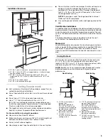
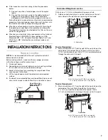
5. If cabinet has recessed bottom, add wood filler strips on each 

side. Install screws to attach filler strips in locations shown.

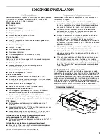
Determine Wiring Hole Location

Cut only one 1

¹⁄₄

" (3.2 cm) diameter wiring access hole. 

1. Determine and clearly mark a vertical centerline on the wall 

and cabinet in the area the vent opening will be made.

To wire through top: 

1. Mark a line distance “A” from the right of the centerline on the 

underside of the cabinet. Mark the point on this line that is 

⁷⁄₈

" (2.2 cm) from back wall. Drill a 1¼" (3.2 cm) diameter hole 

through the cabinet at this point.

To wire through wall:

1. Mark a line distance “A” from the right of the centerline on the 

underside of the wall. Mark the point on this line that 
is 

⁷⁄₈

" (2.2 cm) from the underside of the cabinet. Drill a 

1

¹⁄₄

" (3.2 cm) diameter hole through the rear wall at this point. 

Cabinet
bottom

Wall

3" (7.6 cm)

Wood filler strips

(recessed cabinet

bottoms only)

3" (7.6 cm)

A. Centerline

A. 8

³⁄₈

" (21.3 cm) for 30" (76.2 cm) models

11

³⁄₈

" (28.9 cm) for 36" (91.4 cm) models

A. 8

³⁄₈

" (21.3 cm) for 30" (76.2 cm) models

11

³⁄₈

" (28.9 cm) for 36" (91.4 cm) models

A

Centerline

⁷⁄₈

" (2.2 cm)

from wall,
not cabinet
frame

A

A

Centerline

⁷⁄₈

" (2.2 cm)

Summary of Contents for UXT4030AYS

Page 1: ...lpool ca HOTTE D ASPIRATION DE 30 76 2 CM ET 36 91 4 CM Instructionsd installationetGuided utilisationetd entretien Au Canada pour assistance installation ou service composer le 1 800 807 6777 ou visiter notre site Web à www whirlpool ca Table of Contents Table des matières 2 IMPORTANT READ AND SAVE THESE INSTRUCTIONS FOR RESIDENTIAL USE ONLY IMPORTANT LIRE ET CONSERVER CES INSTRUCTIONS POUR UTILI...

Page 2: ...r l installation 27 UTILISATION DE LA HOTTE 27 Commandes de la hotte de cuisinière 27 ENTRETIEN DE LA HOTTE 28 Nettoyage 28 SCHÉMA DE CÂBLAGE 29 ASSISTANCE OU SERVICE 30 Au Canada 30 Accessoires 30 GARANTIE 31 RANGE HOOD SAFETY You can be killed or seriously injured if you don t immediately You can be killed or seriously injured if you don t follow All safety messages will tell you what the potent...

Page 3: ...zardous or explosive materials and vapors CAUTION To reduce risk of fire and to properly exhaust air be sure to duct air outside do not vent exhaust air into spaces within walls or ceilings attics or into crawl spaces or garages WARNING TO REDUCE THE RISK OF FIRE USE ONLY METAL DUCTWORK WARNING TO REDUCE THE RISK OF A RANGE TOP GREASE FIRE Never leave surface units unattended at high settings Boil...

Page 4: ...Charcoal filter kit For information on ordering see the Accessories section LocationRequirements IMPORTANT Observe all governing codes and ordinances It is the installer s responsibility to comply with installation clearances specified on the model serial rating plate The model serial rating plate is located inside the range hood on the left wall Range hood location should be away from strong draf...

Page 5: ...mper should be on the cold air side of the thermal break The break should be as close as possible to where the vent system enters the heated portion of the house Makeup Air Local building codes may require the use of makeup air systems when using ventilation systems greater than specified CFM of air movement The specified CFM varies from locale to locale Consult your HVAC professional for specific...

Page 6: ... Association One Batterymarch Park Quincy MA 02269 CSA International 8501 East Pleasant Valley Road Cleveland OH 44131 5575 A 120 volt 60 Hz AC only 15 amp fused electrical circuit is required Vent Piece Round 45 elbow 2 5 ft 0 8 m 90 elbow 5 0 ft 1 5 m 7 17 8 cm wall cap 0 0 ft 0 0 m 3 x 10 8 3 cm x 25 4 cm to 7 17 8 cm 4 5 ft 1 4 m 3 x 10 8 3 cm x 25 4 cm to 7 17 8 cm 90 elbow 5 0 ft 1 5 m Maxim...

Page 7: ... model determine which venting method to use roof wall or non vented recirculating 3 Select a flat surface for assembling the range hood Place covering over that surface 4 Lift the range hood and set it upside down onto covered surface 5 If cabinet has recessed bottom add wood filler strips on each side Install screws to attach filler strips in locations shown Determine Wiring Hole Location Cut on...

Page 8: ...abinet 2 Mark lines 5 13 3 cm to the right and left of the centerline on the underside of cabinet 3 Use saber or keyhole saw to cut a rectangular opening for vent To make a circular vent opening on the underside of the cabinet top 1 Mark a centerline on the underside of the top of cabinet 2 Mark a line 5 12 7 cm from the back wall on the underside of the top of cabinet 3 Use a compass or a circle ...

Page 9: ...to place 5 Remove vent knockouts depending on your installation requirements Round vent system installations Remove top rectangular and round vent knockouts Rectangular vent system installations For roof installations remove the top rectangular vent knockout For wall installations remove the rear rectangular vent knockout Non vent recirculating installations Do not remove any knockouts 6 Install 7...

Page 10: ... ordinances There must be enough wiring from the fused disconnect or circuit breaker box to make the connection in the hood electrical terminal box For optional power supply cord kit installations follow the instructions in the Make Electrical Connection section NOTE Do not reconnect power until the installation is complete 2 Remove the screw from the terminal box cover Remove terminal box cover a...

Page 11: ...l minutes after the cooking is complete to clear all smoke and odors from the kitchen The hood controls are located on the front panel of the range hood RangeHoodControls Operating the light Turn the light switch to the right 1 position for Low night light Turn the light switch to the right 2 positions for High Operating the fan The fan is variable speed Rotate the fan switch to the right to turn ...

Page 12: ... filter by placing the back edge in the channel at rear of hood Push filter into place turn the filter retainer to secure filter to range hood 5 Replace screw in the grease filter retainer For non vented recirculating installations The charcoal filter is not washable It should last up to 6 months with normal use 1 Replace metal grease filter with a charcoal filter For information on ordering see t...

Page 13: ... Power Supply 120 VAC Frequency 60 Hz Amperage Wattage Rating Motor Resistance White Red White Black Lamp Switch Off Low High Motor Switch Off On Lamp Switch Operation 1 3 Low 1 2 Off 1 L High Ground Screw GND L N BK W R Speed 2 Common Speed 1 R W NOTE Speed 1 not used R BK BK R BK W BK W Y Rectifier Diode ...

Page 14: ... company in your area you can also look in your telephone directory Yellow Pages For further assistance If you need further assistance you can write to Whirlpool Corporation with any questions or concerns at Whirlpool Brand Home Appliances Customer eXperience Center 553 Benson Road Benton Harbor MI 49022 2692 Please include a daytime phone number in your correspondence InCanada Call the Whirlpool ...

Page 15: ...ice by an authorized Whirlpool servicer is not available 10 The removal and reinstallation of your major appliance if it is installed in an inaccessible location or is not installed in accordance with published installation instructions 11 Major appliances with original model serial numbers that have been removed altered or cannot be easily determined This warranty is void if the factory applied s...

Page 16: ...16 Notes ...
Page 17: ...as de non respect des instructions Votre sécurité et celle des autres est très importante Nous donnons de nombreux messages de sécurité importants dans ce manuel et sur votre appareil ménager Assurez vous de toujours lire tous les messages de sécurité et de vous y conformer AVERTISSEMENT DANGER Voici le symbole d alerte de sécurité Ce symbole d alerte de sécurité vous signale les dangers potentiel...

Page 18: ...die et évacuer adéquatement les gaz veiller à acheminer l air aspiré par un conduit jusqu à l extérieur ne pas décharger l air aspiré dans un espace vide du bâtiment comme une cavité murale un plafond un grenier un vide sanitaire ou un garage AVERTISSEMENT POUR RÉDUIRE LE RISQUE D INCENDIE UTILISER UNIQUEMENT DES CONDUITS MÉTALLIQUES AVERTISSEMENT POUR MINIMISER LE RISQUE D UN FEU DE GRAISSE SUR L...

Page 19: ...commander des pièces voir la section Accessoires Exigencesd emplacement IMPORTANT Observer les dispositions de tous les codes et règlements en vigueur C est à l installateur qu incombe la responsabilité de respecter les distances de séparation exigées spécifiées sur la plaque signalétique de l appareil La plaque signalétique est située à l intérieur de la hotte sur la paroi de gauche Installer la ...

Page 20: ...e toit Installations dans les régions au climat froid On doit installer un clapet anti reflux supplémentaire à l arrière pour minimiser le reflux d air froid et incorporer un élément d isolation thermique pour minimiser la conduction de chaleur par l intermédiaire du conduit d évacuation de l intérieur de la maison à l extérieur Le clapet anti reflux doit être placé du côté air froid de la résista...

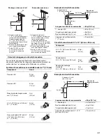
Page 21: ...ssus achat séparé B Bouche de décharge murale avec clapet achat séparé C Entre 18 45 7 cm min et 24 61 cm max au dessus de la surface de cuisson Composant Rond Coude à 45 2 5 pi 0 8 m Coude à 90 5 0 pi 1 5 m Bouche de décharge murale de 7 17 8 cm 0 pi 0 0 m 3 x 10 8 3 cm x 25 4 cm à 7 17 8 cm 4 5 pi 1 4 m Raccord coudé à 90 de 3 x 10 8 3 cm x 25 4 cm à 7 17 8 cm 5 0 pi 1 5 m A B C A B C Longueur m...

Page 22: ...alétique de l appareil est située derrière le filtre sur la paroi arrière de la hotte Le calibre des conducteurs doit satisfaire aux exigences de la plus récente édition de la norme National Electrical Code ANSI NFPA 70 ou de la norme CSA C22 1 94 Code canadien de l électricité partie 1 et C22 2 n 0 M91 dernière édition et de tous les codes et règlements en vigueur INSTRUCTIONS D INSTALLATION Prép...

Page 23: ...ur découper l ouverture rectangulaire du système d évacuation dans le mur Style 2 Découpages d ouverture pour un conduit rectangulaire de 3 x 10 8 3 x 25 4 cm sur raccord de transition rond Décharge à travers le toit Découpage d une ouverture rectangulaire de 4 x 10 10 8 cm x 26 7 cm sur la face inférieure du bas du placard 1 Tracer des lignes à 1 3 cm et 4 12 1 cm du mur arrière sur l axe central...

Page 24: ...la bouche de décharge à l extérieur à travers le mur ou le toit Installationdelahotte REMARQUE Votre modèle comporte un clapet anti reflux rectangulaire de 3 x 10 8 3 x 25 4 cm à l intérieur de la hotte 1 Retirer le clapet anti reflux rectangulaire de 3 x 10 8 3 x 25 4 cm fixé avec des vis de 3 5 x 9 5 mm à l intérieur de la hotte Utiliser ces vis pour installer le clapet anti reflux rectangulaire...

Page 25: ...gulaire de 3 x 10 8 3 x 25 4 cm jusqu à 1 2 5 cm de chaque côté du centre de la hotte pour pouvoir installer les conduits décentrés Si un clapet anti reflux est monté avec une bouche murale de décharge elle même équipée d un clapet anti reflux vérifier qu ils ne se gênent pas mutuellement En cas d interférence retirer l obturateur à registre du connecteur de conduit Installation sans décharge à l ...

Page 26: ...acultatif suivre les instructions de la section Raccordement électrique REMARQUE Ne pas mettre le système sous tension avant d avoir complètement terminé l installation 2 Ôter la vis du couvercle du boîtier de connexion Retirer le couvercle du boîtier de connexion et le mettre de côté 3 Ôter l opercule pour le passage de l alimentation électrique du sommet ou de l arrière de la hotte de ventilatio...

Page 27: ...teur de la hotte en marche avant d entreprendre une cuisson et laisser le ventilateur fonctionner pendant plusieurs minutes après l achèvement d une cuisson pour pouvoir évacuer de la cuisine toute trace d odeur de cuisson ou de fumée Les commandes de la hotte sont situées sur la face avant de la hotte Commandesdelahottedecuisinière Pour faire fonctionner la lampe Pousser le commutateur d éclairag...

Page 28: ...le filtre 3 Laver les filtres métalliques selon le besoin au lave vaisselle ou avec une solution de détergent chaude 4 Réinstaller le filtre en plaçant le bord arrière dans la rainure à l arrière de la hotte Enfoncer le filtre faire pivoter la patte de retenue du filtre pour fixer le filtre à la hotte 5 Réinstaller la vis dans la patte de retenue du filtre à graisse Installations sans décharge à l...

Page 29: ...ble 1 2 Arrêt 1 L Élevé L Neu N BL R R BL REMARQUE Vitesse 1 non utilisée R N N R N BL N BL JA Diode redresseuse Vitesse 2 Commun Vitesse 1 1 2 10 A 73 10 Watts 17 1 10 Ohms 13 6 10 Ohms Caractéristiques du moteur Alimentation électrique 120 VCA Fréquence 60 Hz Intensité Puissance nominale Résistance du moteur Blanc Rouge Blanc Noir Vis de mise à la terre Terre ...

Page 30: ... gamme d appareils électroménagers Consignes d utilisation et d entretien Ventes d accessoires et de pièces de rechange Références aux marchands locaux aux distributeurs de pièces de rechange et aux compagnies de service Les techniciens de service désignés par Whirlpool Canada LP sont formés pour remplir la garantie des produits et fournir un service après la garantie partout au Canada Pour plus d...

Page 31: ...en Whirlpool autorisé n est pas disponible 10 La dépose et la réinstallation de votre gros appareil si celui ci est installé dans un endroit inaccessible ou n est pas installé conformément aux instructions d installation fournies 11 Les gros appareils ménagers dont les numéros de série et de modèle originaux ont été enlevés modifiés ou qui ne peuvent pas être facilement identifiés La présente gara...

Page 32: ...W10400322C 2011 All rights reserved Tous droits réservés 8 11 Printed in Mexico Imprimé au Mexique ...

Reviews: