
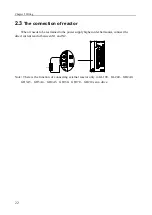
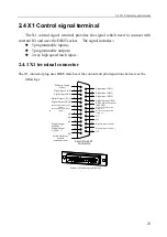


2.4 X1 Control signal terminal
23
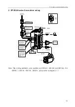
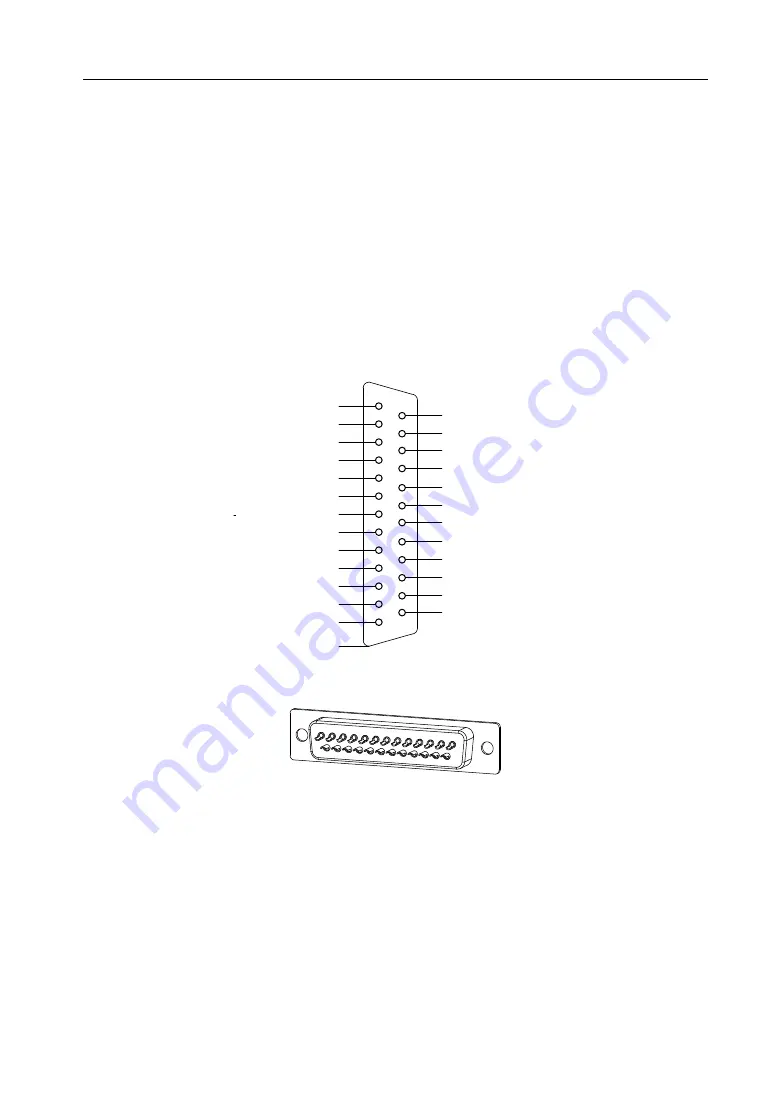
2.4 X1
Control signal terminal
The X1 control signal terminal provides the signal which need to connect with
external IO, and uses the DB25 socket. The signal includes:
:
5 programmable inputs;
;
5 programmable outputs
;
2 way high speed latch input.
。
2.4.1 X1 terminal connector
The X1 connector plug uses DB25 male head, the contour and pin disposition charts are as the
followings:
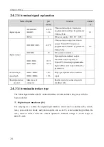
DI Power Supply
(COM+)
Digital Input 1(DI1)
Digital Input 2 (DI2)
Digital Input 3(DI3)
Digital Input 4(DI4)
Digital Input 5(DI5)
Digital Output 1(DO1)
Digital Output 2(DO2)
Digital Output 3(DO3)
DO Common Terminal
(DOCOM)
Position high speed latch 2-
(HDI2-)
Shiled Protection
Ground
(connector case)
1
2
3
4
5
6
7
8
9
10
11
12
13
25
24
23
22
21
20
19
18
17
16
15
14
Servo Drive X1
Connector
Position high speed latch
2+(HDI2+)
Position high speed latch
1+(HDI1+)
NC
NC
Digital Output 4-(DO4-)
Digital Output 5-(DO5-)
NC
Position high speed latch 1-
(HDI1-)
NC
NC
Digital Output
4+(DO4+)
Digital Output
5+(DO5+)
NC
NC
25
13
1
14
Connector X1 Soldering Lug Disposition
Summary of Contents for EP3E Series
Page 10: ......


