VP30/VP500
MAINTENANCE INFORMATION
Starting compressor after Maintenance
Turn the compressor by hand for a few revolutions. Check that the motion is smooth and free.
Re-check all screws and connections for tightness.
Run the compressor for 10 - 15 minutes until warm.
Re-check all screws and connections for tightness.
General maintenance notes
Delivery valves will wear out before suction valves, due to the higher temperatures.
When replacing piston rings, ALWAYS replace as a complete set for each stage (i.e. do not mix old
and new rings in the same cylinder)
Always lubricate components (not paper gaskets) on assembly with clean lubricating oil.
Make sure that cylinders and cylinder head components are extremely clean on assembly. Any
particles of dirt left inside can score the cylinder bores and reduce the performance of the
compressor valves.
Troubleshooting
Low output flow or pressure
Leakage
If gas is leaking from the compressor cylinders or coolers, the output flowrate will fall, resulting in
low pressure. Carry out leakage test.
1st stage cylinder head
If the 1st stage cylinder head gasket is leaking, or the valve plate gasket is damaged, the flowrate
will fall. Check that the gaskets 5/9 and 5/11 are correctly fitted, and in good condition.
Unloader system
If the unloader valves do not seat correctly, gas from the compressor will vent through the unloader
vent when the compressor is running. With the compressor running, check that
no gas is venting through the unloader vent. If there is gas venting when the
compressor is running, carry out the unloader inspection and replace any worn
components.
Worn piston rings
Worn piston rings will reduce the output capacity of the compressor. Replace the
piston rings.
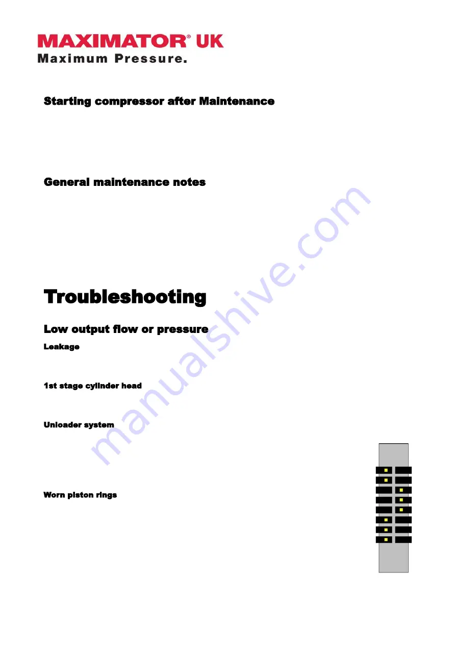
Piston rings marked ‘TOP’ or with a coloured dot, must be installed with the
‘TOP’/ dot marks facing the top of the piston.
Illustration is used to show orientation marks on piston rings only.
IMPORTANT:
Piston ring gaps must be rotated through 90 or 120 degrees from each other.
July 21
12 of 42
Summary of Contents for VP30
Page 15: ...VP30 VP500 MAINTENANCE INFORMATION Fig 2 Crankcase July 21 15 of 42 ...
Page 17: ...VP30 VP500 MAINTENANCE INFORMATION Fig 3 Crankcase July 21 17 of 42 ...
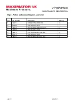
Page 19: ...VP30 VP500 MAINTENANCE INFORMATION Fig 4 Piston and connecting rod July 21 19 of 42 ...
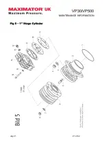
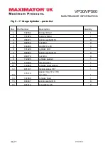
Page 21: ...VP30 VP500 MAINTENANCE INFORMATION Fig 5 1st Stage Cylinder July 21 21 of 42 ...
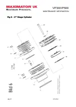
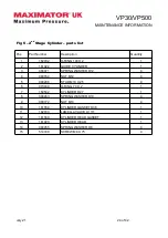
Page 23: ...VP30 VP500 MAINTENANCE INFORMATION Fig 6 2nd Stage Cylinder July 21 23 of 42 ...
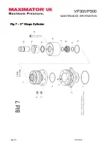
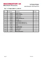
Page 25: ...VP30 VP500 MAINTENANCE INFORMATION Fig 7 3rd Stage Cylinder July 21 25 of 42 ...
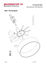
Page 27: ...VP30 VP500 MAINTENANCE INFORMATION Fig 8 Fan and guard July 21 27 of 42 ...
Page 29: ...VP30 VP500 MAINTENANCE INFORMATION Fig 9 Coolers July 21 29 of 42 ...
Page 31: ...VP30 VP500 MAINTENANCE INFORMATION Fig 10 Unloader Manifold July 21 31 of 42 ...
Page 34: ...VP30 VP500 MAINTENANCE INFORMATION Fig 11 Unloaders July 21 34 of 42 ...
Page 36: ...VP30 VP500 MAINTENANCE INFORMATION Fig 12 Oil Lubrication July 21 36 of 42 ...
Page 38: ...VP30 VP500 MAINTENANCE INFORMATION Fig 13 Crankcase Breather July 21 38 of 42 ...
Page 40: ...VP30 VP500 MAINTENANCE INFORMATION Fig 14 Motor July 21 40 of 42 ...


