


MAX32600 User’s Guide
System Configuration and Management
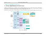
4.1 Power Ecosystem and Operating Modes
Note
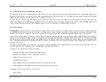
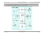
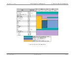
Power mode transition restrictions dictate measurement sequences. Further transitioning information is found in the power mode sections below.
The following is a typical measurement sequence: LP0/LP1
→
LP3
→
LP2
→
LP3
→
LP0/LP1
Figure 4.1: Power State Diagram
Rev.1.3 April 2015
Maxim Integrated
Page 30