


MAX32600 User’s Guide
Introduction
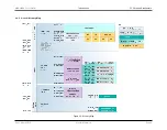
2.4 Clock Inputs
2.4
Clock Inputs
Configuration of time delays are necessary to ensure that the
MAX32600
always switches to a valid clock; reference the
section for detailed
information.
2.4.1
External High Frequency Crystal
The
MAX32600
includes a high-frequency crystal oscillator circuit designed to operate with an external crystal. Fundamental mode crystals can be used with the
oscillator circuit up to a frequency of 24MHz. External load capacitors are required depending on the crystal specifications.
An external clock source may also be used by the
MAX32600
in place of a high-frequency crystal. For this configuration, the external clock source (which must meet
the electrical/timing requirements given in the datasheet) is connected to the part on the HFXIN pin and the HFXOUT pin is left floating.
2.4.2
32kHz Crystal Oscillator
A 32kHz crystal oscillator (with the 32kHz crystal connected between the 32KIN and 32KOUT pins) is used to generate the 32kHz clock that is used by the Real
Time Clock module.
An external clock source may also be used by the
MAX32600
in place of a 32kHz crystal. For this configuration, the external clock source (which must meet the
electrical/timing requirements given in the datasheet) is connected to the part on the 32KIN pin.
2.4.3
48MHz USB Clock PLL
The phase locked loop (PLL) clock generation circuit is used to generate a 48MHz clock which is required for proper operation of the USB device interface. If the
USB interface will not be used, then use of the PLL is optional.
The PLL generates a 48MHz clock using a clock multiplier circuit, which has a 2X mode for use with a 24MHz crystal, a 4X mode for use with a 12MHz crystal, and
a 6X mode for use with an 8MHz crystal. The output of the PLL can be used as a system clock source (after dividing it by two) with a 24MHz frequency.
2.4.4
Internal 24MHz Trimmed Relaxation Oscillator
An internal trimmed relaxation oscillator generates a 24MHz (
±
1%) clock which can be used as a system clock source. If the USB interface will be used, the PLL is
used to generate a 48MHz (
±
0.25%) clock. The input clock to the PLL can be an external crystal, an external digital clock source, or the internal relaxation oscillator
can be used if a 32kHz crystal is available to frequency trim the relaxation oscillator.
For optimal performance, the ADC requires a more stable clock source (with less jitter) than can be provided by the relaxation oscillator; the high frequency crystal
oscillator must be used as a system clock source when the ADC is in use. However, in lower sample rate applications, the relaxation oscillator can be used as the
ADC clock source.
Rev.1.3 April 2015
Maxim Integrated
Page 12