background image

www.max-power.com 

17 


 INSTALLATION MANUAL CT550 


The warranty as outlined above is only applicable to Max Power manufactured thrusters and 

optional equipment as used in marine pleasure industry. The supplier holds the exclusive right 

to test the product and determine whether it is defective 


Warranty Terms 


If the material is used for anything other than for pleasure craft, the guarantee is limited to a 
six-month period. 


Year 1 - All factory testing, diagnosis, repairs and replacements are performed at no charge 

to the End User. All parts and up to two hours of labor are covered for repairs and 
replacements conducted in the field. 


Year 2 - All factory testing, diagnosis, repairs and replacements are performed at no charge 

to the End User. This excludes any damage or faults occurring from normal wear and 
tear on the following items: engine, oil seals, relay contacts(If warranty is registered 
within the 3 month period following installation) 

Warranty Exclusions 


Damage due to modifications or installation contrary to published specifications 
Cost of hauling the boat 
Damage due to repairs performed by an unauthorized service centre 
Damage due to lack of normal maintenance services 
Damage due to water 
Parts replaced due to normal wear and tear 
Repairs performed without knowledge of manufacturer (please contact dealer to receive 
Repair Authorization Number) 
Tampering of equipment by the End User 
Cost of travel to and from the job site 
Cost of economic loss, including injury to any person, damage to property, loss of income or 
profit, communication, lodging, inconvenience 
Consequential damage due to failure, including those arising from collision with other vessels 
or objects 

Procedural Guidelines 


PLEASE VIEW THE TROUBLE SHOOTING LIST TO ASCERTAIN OR SOLVE ORIGIN OF 
PROBLEM PRIOR TO CONTACTING THE DEALER/INSTALLER 


1) 

Contact your dealer/installer to report the problem. 

a. 

If you do not know who this is contact the nearest Max Power distributor 

b. 

If you are in foreign waters please contact the nearest Max Power distributor 

2) 

Ensure you have your serial number and model number to hand (top right hand 
corner of warranty) 

3) 

Dealer/Installer will come to site to decipher the cause of the fault 

4) 

If the cause of fault is due to a manufacturing problem the dealer will contact Max 
Power to receive Repair Authorization Number. 

5) 

If the problem is due to an installation error please contact your installer. 


PLEASE TAKE PHOTOGRAPHS TO SHOW THE PROBLEM, IF POSSIBLE

Summary of Contents for CT550

Page 1: ... CT550 MANUAL INSTALATION OPERATION MAINTENANCE Last update June 2020 Serial N Date of Installation IT IS IMPORTANT TO KEEP THIS MANUAL ON BOARD Address 5 Via Philips Str 20900 Monza MI Italy Tel 39 039 2001973 Fax 39 039 2004299 ...

Page 2: ... GRILLS 6 7 HYDRAULIC general remarks 7 8 HYDRAULIC SPECIFICATIONS 8 9 MAINTENANCE 8 10 CT550 PART LIST 10 11 WIRING DIAGRAM 12 12 HYDRAULIC DIAGRAM 13 13 POSITIONING AND MESURMENTS 14 14 PROPELLER ASSEMBLY 15 15 MAIN DIMENSIONS 16 16 WARRANTY COVERAGE 17 Definitions 17 Period of Coverage 17 Warranty Registration 17 Warranty Terms 17 Warranty Exclusions 17 Procedural Guidelines 17 ...

Page 3: ...king place For any boat requiring official classification bodies of approval should also be consulted at the earliest opportunity In any case all other bodies governmental or otherwise should be contacted to ensure conformity with legal regulations relating to the boat in question Congratulations on choosing a Max Power thruster Characterised by its performance durability reliability and ease of i...

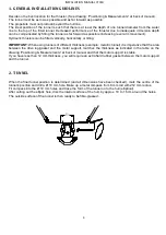
Page 4: ...ferent thickness example metallic tunnel it is imperative that the area between the drive leg gasket and the motor support matches the thickness as indicated in the table on the drawing Positioning Measurements at back of manual and that the motor support is stable If you have less than 12 mm thickness you will require an extra hard rubber gasket between the motor support and the tunnel 2 TUNNEL W...

Page 5: ...plete apply a coat of epoxy or gel coat to waterproof the entire area 3 PROPELLER DRIVE LEG MOTOR SUPPORT The leg s gasket and the motor s support can be used to mark up the drilling position in some cases it might be easier to mark out the position and drill before the stratification of the tunnel Centre and trace the drilling positions for the leg and its support Fit the leg along with the gaske...

Page 6: ...er to ensure maximum gripping between them Check that the propellers turn freely and that there is no tight spot A certain amount of resistance is normal from the motor When all is assembled recheck the tightness of all the motor bolts NOTE The coupling on the motor side is in place when delivered do not touch this 5 PROPELLERS The positioning of the propellers is indicated at the end on chapter P...

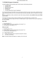
Page 7: ...nce make sure that the return filter is easily accessible An isolation valve can be fitted to the suction The pump can be driven only by internal combustion engine crankshaft pulley or gearbox PTO For an internal combustion engine with fixed or variable speed 2 types of pumps can be used depending on the unit to be fitted Direct PTO 1 Fixed flow pump 2 Variable displacement pump depending on the m...

Page 8: ...d directly back into the top of the oil tank Use synthetic mineral or vegetable hydraulic oil to ISO standard 32 to 48 8 HYDRAULIC SPECIFICATIONS CT550 Specifications Power 49 KW Pressure 250 bar Flow 125 141 lt min Detailed instructions and diagrams are delivered with each pack specific to the installation chosen 9 MAINTENANCE In order to ensure peak performance from your thruster the tunnel the ...

Page 9: ...INSTALLATION MANUAL CT550 9 Installation Notes THE MAX POWER TEAM WISHES YOU SUCCESSFUL MANOEUVRING AND ENJOYABLE CRUISING IT IS IMPORTANT TO KEEP THIS MANUAL ON BOARD ...

Page 10: ...INSTALLATION MANUAL CT550 10 10 CT550 PART LIST ...

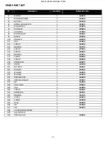
Page 11: ...1 631753 14 CIRCLIP 2 635425 15 CIRCLIP 1 636136 16 BEARING 1 636131 17 PINION 1 636239 18 CIRCLIP 1 636136 19 SCREW M10 2 633637 20 ANODE 2 636138 21 NUT M20 2 636141 22 WASHER 2 636142 23 WASHER 2 636222 24 WASHER 2 636140 25 PROPELLER RH 1 636243 26 PROPELLER SHAFT 2 636237 27 KEY 2 632050 28 SEAL shield 2 636235 29 SEAL 2 630859 30 CIRCLIP 2 635232 31 SCREW M8 12 635721 32 BEARING 4 631744 33 ...

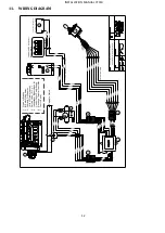
Page 12: ...able C onnector C able C onnector Ye l l o w Ye l l o w C able C onnector Yellow W hite Red Brown Blue Black Yellow Yellow Yellow Grey Grey W hite Red Brown Blue Black Red Black Yellow Yellow Red Black Yellow Yellow Red Black Bl a ck Bro wn Bl u e W h i te Re d Black Brown Blue W hite Red Yellow Yellow Black Red White Red Black Brown Blue 6 A B C 2 x 2 mm Depending on cable lenght 1 Clutch or Bypa...

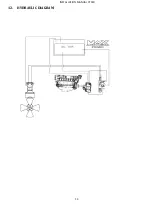
Page 13: ...INSTALLATION MANUAL CT550 13 12 HYDRAULIC DIAGRAM ...

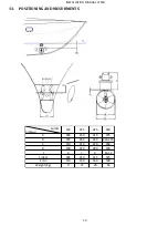
Page 14: ...T550 14 13 POSITIONING AND MESURMENTS MODEL DIM mm 125 225 325 550 A 185 250 315 375 B 197 264 333 420 430 C 210 210 220 249 D 190 220 280 378 T 6 7 9 12 14 E ideal 185 250 315 375 E min 110 140 160 190 Weight Kg 9 12 20 65 ...

Page 15: ... washer for M20 into the shaft This washer is to center the anode Center the washer on the propeller shaft 3 Insert the lock washer into the slot of the propeller shaft 4 Use Loctite 243 medium grade on the thread of the propeller shaft 5 Insert the nut M20 on the propeller shaft and screw it Max 180Nm tightening torque ...

Page 16: ...6 6 Insert the anode on the shaft The anode in centered by the washer M20 Then screw the hd cap screw M10x25 on the propeller shaft putting on the thread of the screw a few quantity of Loctite 243 medium grade 15 MAIN DIMENSIONS ...

Page 17: ...ommercial use i e Charter boats or work boats Resellers Max Power approved distributors and dealers Serial Number Number in upper right hand corner of Warranty document Supplier The manufacturer Max Power Warranty The terms and conditions that are covered by the manufacturer Period of Coverage The equipment manufactured by the Supplier is guaranteed to be free from defective workmanship components...

Page 18: ...Damage due to lack of normal maintenance services Damage due to water Parts replaced due to normal wear and tear Repairs performed without knowledge of manufacturer please contact dealer to receive Repair Authorization Number Tampering of equipment by the End User Cost of travel to and from the job site Cost of economic loss including injury to any person damage to property loss of income or profi...

Page 19: ...18 ...

Reviews: