


9
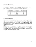
1.1 Before getting Started
It is the sole responsibility of the purchaser of Matrix Fitness Systems products to instruct all
individuals, whether they are the end user or supervising personnel, on proper usage of the equipment. It
is recommended that all users of Matrix Fitness Systems exercise equipment be informed of the
following information prior to its use.
1.2 proper usage
1.
Do not use the equipment in any way other than designed or intended by the manufacturer. It is
imperative that all Matrix Fitness Systems equipment is used properly to avoid injury.
2.
Keep hands and feet clear of moving parts at all times to avoid injury.
3.
Unsupervised children must be kept away from this equipment.
4.
Do not wear loose clothing while on equipment.
5.
When it is necessary to immobilize the treadmill, set the display to read “CHOOSE PROGRAM
USING QUICK KEYS OR SPEED UP OR DOWN KEYS”, then hold down the RESET &
ENTER keys. The treadmill will now display “IMMOBILIZED.” In this state the treadmill can
not be operated; both the drive motor & elevation motor are disabled. The treadmill will remain in
this state across power cycles, resets, etc. To return to normal operation mode repeat the same key
sequence, hold down the RESET & ENTER keys. The display will now read “CHOOSE
PROGRAM USING QUICK KEYS OR SPEED UP OR DOWN KEYS”
Summary of Contents for MX-T3x
Page 1: ...1 MX T3x TM94E AC SYSTEM SERVICE MANUAL...
Page 4: ...4 SERIAL NUMBER LOCATION SECTION 1...
Page 5: ...5 Matrix T3x TM94E Serial Number Location...
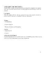
Page 6: ...6 MOVING THE UNIT SECTION 2...
Page 8: ...8 IMPORTANT SAFETY I N S T R U C T I O N S SECTION 3...
Page 12: ...12 PREVENTATIVE MAINTENANCE SECTION 4...
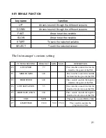
Page 19: ...19 SECTION 5 MANAGER MODE...
Page 23: ...23 SECTION 6 TROUBLE SHOOTINGS...
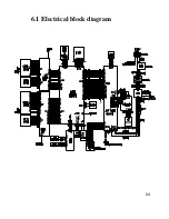
Page 24: ...24 6 1 Electrical block diagram...
Page 25: ...25 6 2 Wire pin definition P01 Console Wire...
Page 26: ...26 P04 Inverter Wire N24 Pulse Board Wire...
Page 27: ...27 P11 CTRL Overlay Wire Left P12 CTRL Overlay Wire Right...
Page 35: ...35...
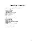
Page 39: ...39 SECTION 7 PARTS REPLACEMENT...
Page 42: ...42 Figure D Figure E...
Page 53: ...53 Figure D Figure E Figure F Figure G...
Page 57: ...57 Install the MSP430 Tools Computer...
Page 58: ...58 Press the Load Image Installation software to MSP430 Tools...
Page 59: ...59 Installing the MSP430 cable to console MSP430...
Page 61: ...61 SECTION 8 UPGRADES...