


20
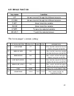
ENGINEERING MODE
Engineering screens allow the viewing and editing of variables that would be necessary
for a club operator/manager to customize. Unless otherwise noted, engineering screens
consist of the initial screen, the editing or action screen, and the saving screen. The
initial screen displays the variable type, and in most cases, the current value. Edit or
action screens are where the editing of the variable take place. The saving screen
indicates the variable is being saved.
To access the Engineering screens press and hold the
ELEVATION UP
and
SPEED
DOWN
buttons for three seconds. The display will now display 'Engineering Mode'.
Use the
ELEVATION UP
or
DOWN
arrows to scroll through the different engineering
screens.
Press
SELECT
to edit the selected engineering screen.
Use the
SPEED UP
or
DOWN
arrows to set the variable.
Press
START
to save the selected variable.
MX-T3x OPERATION MANUAL- Engineer mode
How to enter into the engineering mode?
1. Press & Hold both “ELEVATION
UP” and “SPEED DOWN” at the
same time for 3-5 sec. Then, the
display will show “MANAGER
MENU”.
2. Press the "ELEVATION UP or
DOWN" to select you want and press
the “SELECT" key enter.
Summary of Contents for MX-T3x
Page 1: ...1 MX T3x TM94E AC SYSTEM SERVICE MANUAL...
Page 4: ...4 SERIAL NUMBER LOCATION SECTION 1...
Page 5: ...5 Matrix T3x TM94E Serial Number Location...
Page 6: ...6 MOVING THE UNIT SECTION 2...
Page 8: ...8 IMPORTANT SAFETY I N S T R U C T I O N S SECTION 3...
Page 12: ...12 PREVENTATIVE MAINTENANCE SECTION 4...
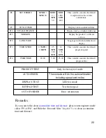
Page 19: ...19 SECTION 5 MANAGER MODE...
Page 23: ...23 SECTION 6 TROUBLE SHOOTINGS...
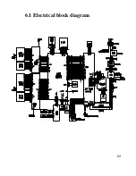
Page 24: ...24 6 1 Electrical block diagram...
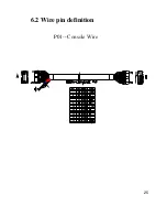
Page 25: ...25 6 2 Wire pin definition P01 Console Wire...
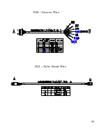
Page 26: ...26 P04 Inverter Wire N24 Pulse Board Wire...
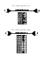
Page 27: ...27 P11 CTRL Overlay Wire Left P12 CTRL Overlay Wire Right...
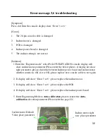
Page 35: ...35...
Page 39: ...39 SECTION 7 PARTS REPLACEMENT...
Page 42: ...42 Figure D Figure E...
Page 53: ...53 Figure D Figure E Figure F Figure G...
Page 57: ...57 Install the MSP430 Tools Computer...
Page 58: ...58 Press the Load Image Installation software to MSP430 Tools...
Page 59: ...59 Installing the MSP430 cable to console MSP430...
Page 61: ...61 SECTION 8 UPGRADES...