


8
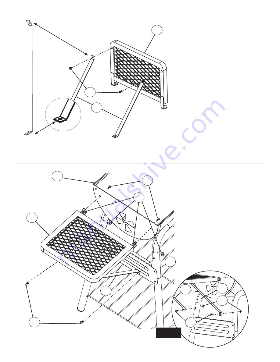
STEP 7.
Note: Position brackets so sharper
angled end (Fig. A) is used to con-
nect to leg connector.
Attach side shelf support brackets
(14) to side shelf (15) using phillips
head screws (D).
Do not fully tighten at this time.
STEP 8.
Align holes on assembled side shelf
(15) with holes on grill body (5) and leg
connector (7) as shown.
Insert phillips head screw (D) through
holes on body (5) into side shelf (15).
Secure using hex flange nuts (C).
Attach shelf support brackets (14) to
top holes in leg connector (7) as shown
in illustration and Fig. A. using phillips
head screws (A). Secure using hex
flange nuts (C).
Do not fully tighten screws at this
time.
D
7
C
A
5
15
14
14
A
C
7
Fig. A
D
15
14
Fig. A