

6 |
P a g e
Helios 75K Floodlight System – User Manual
4.3.
Instructions for installing/removing the Light Panel into/from the reactor vessel
4.3.1.
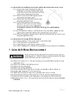
Ensure all electrical connections are tight, the
Carabiners are securely attached, slack exists
in the cable between the Light Panel and strain
relief, and the light functions normally.
4.3.2.
Perform a final visual FME inspection of all
components entering the water.
4.3.3.
Slowly lower the Light Panel into the water
using the Light Panel Cable.
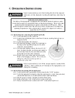
4.3.4.
Position the Light Panel near the inside
diameter of the reactor vessel and continue
lowering to the desired level.
Master-Lee
recommends a distance of 2-10’ below the flange for optimal lighting
coverage.
4.3.5.
IF the Light Panel interferes with movement of fuel assemblies, THEN carefully
reposition the Light Panel until the fuel assemblies have been moved.
4.3.6.
When activities are completed, slowly raise the Light Panel from the reactor vessel
using the Light Panel Cable.
4.4.
Instructions for turning OFF the light panel
4.4.1.
Depress the Power “I/O” rocker switch to turn off the light.
4.4.2.
Verify the panel is not emitting light.
4.4.3.
Unplug the power cord from the electrical outlet.
4.4.4.
Allow a minimum of 15 minutes for the light panel to cool down prior to handling.
5.
L
ENS
&
O-R
ING
R
EPLACEMENT
Power cord must be disconnected from an electrical source prior to
performing service. Failure to remove electrical potential to the light
panel will increase the risk of electric shock.
5.1.
Remove the twelve (12) ¼”-20 socket head cap screws and Nordlock washers from the
light panel cover.
5.2.
Remove the stainless steel light panel cover.
5.3.
Remove the lens and dispose.
5.4.
Remove the O-ring and dispose.
5.5.
Clean and inspect the O-ring groove for signs of degradation, debris, damage, etc.
5.6.
Lightly apply Molykote 111 to the new O-ring.
5.7.
Install the new O-ring into the groove ensuring it does not twist or kink.
5.8.
Clean and inspect the new lens (verify free of cracks, scratches, discoloration, etc.).
5.9.
Install the lens and stainless steel light panel cover, aligning with the mount holes.
5.10.
Install the twelve (12) ¼”-20 socket head cap screws and Nordlock washers and
torque
to 40 in-lb
.


