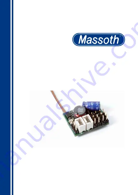
eMOTION 8FS Servodecoder
eMOTION 8FS Servo Decoder
8152501
Page 1: ...eMOTION 8FS Servodecoder eMOTION 8FS Servo Decoder 8152501 ...
Page 2: ... Spannung entspre chend der CV Liste richtig eingestellt ist Für Schäden durch Nichtbeachtung dieses Hinweises übernehmen wir kei ne Haftung Dear customer we strongly recommend that you read this manu als and the warning notes thoroughly before installing and operating your decoder Note concerning the function outputs The function outputs are set per default to full track voltage Make sure the CVs...
Page 3: ...aten Garantie Reparatur Kundendienst Hotline Table of Contents Summary of Functions Scope of Supply Hook Up Track Connection Connecting the function outputs Function Outputs A1 A4 Function Outputs A5 A6 Function Outputs A7 A8 Powercap Power buffers Getting started Basic factory default settings Programming Locomotive address Programming lock CV 15 16 Programming address CV 107 108 Function outputs...
Page 4: ...Werte Überlastschutz für alle Funktionen 1 1Lieferumfang eMOTION 8FS Decoder Klebepad Steckerleiste Bedienungsanleitung 1 Summary of Functions 8 function outputs 6 not reinforced 2 reinforced open collector integrated 5 5V voltage regulation for servo operation handles servos Massoth Motor drives Massoth Uncouplers LEDs and bulbs BufferControl Powercaps etc connection to track via 2 leads solderin...
Page 5: ...nsausgänge A1 A4 A7 A8 bis 10mA belastbar geschaltet gegen DEC A5 A6 bis 100mA belastbar geschaltet gegen DEC 2 Hook Up Install your decoder in compliance with the connecting diagrams in this manual The decoder is protected against shorts and excessive loads However in case of a connection error e g a short between a light and the motor this safety feature cannot work and the decoder will be de st...
Page 6: ...uert werden 2 3Function Outputs A1 A4 These outputs can be used diffe rently as a standard function output 5V re GND or direct connection of a servo The pin assignment are shwon in figure 1 All outputs can be operated in end positioning mode with start and end position Besides that outputs A3 and A4 can be used in speed step mode to individually control the position with the controller wheel knob ...
Page 7: ... zwischen den beiden program mierten Endpunkten position CV s Two operation types are available which are set with the special functions Switching between endpoints Function off lower endpoint Function on upper endpoint individual positioning with controller Function off Servo remains Function on Servo operates with the controller between the two programmed end points Dec 5V Dec schwarz black Dec ...
Page 8: ... CV 29 Bit 2 der Analogbetrieb gesperrt werden Den Anschluss entnehmen Sie der Bedienungsanlei tung des Powercaps 2 4Function Outputs A5 A6 These two function outputs are located on one three pin outlet They are triggered to DEC max 22V with a max load of 100mA 2 5Function Outputs A7 A8 These two function outputs 5V are specially designed to operate the Massoth Uncoupler 8414002 The three pin plug...
Page 9: ...ler Der eMOTION 8FS Decoder reagiert nur auf parallele Funktionsauslö sung Die alte serielle Funktionsaus lösung wird nicht unterstützt 3 Getting started 3 1Basic factory default settings The basic factory default settings of the eMOTION 8FS decoder are shown in the following table Basic settings Function decoder Locomotive address 3 Speed steps 28 Function outp voltages A1 4 7 8 5V A5 6 22V Funct...
Page 10: ...239 in CV 17 CV 18 zusätzlich muss in diesem Fall CV 29 BIT 5 an sein Man berechnet wie folgt CV 17 Adresse 256 4 Programmierung This chapter focuses on major CVs that are very important and required to be set correctly to ensure proper operation These programming modes are supported CV write CV read Register POM IMPORTANT NOTE FOR PROGRAMMING To program the decoder it needs to be connected to the...
Page 11: ... Sie wissen den Wert von CV 16 nicht mehr so können Sie mit CV 7 16 die Programmiersperre zurücksetzen Nach erfolgreicher Einstellung Ihres 8FS Decoders unbedingt die Programmiersperre setzen Multiple Unit addresses 1 99 in CV 19 4 2Programming Lock CV 15 16 To prevent unintentional pro gramming this decoder offers a programming lock in CV 15 16 If CV 15 matches CV 16 programming is possible If CV...
Page 12: ... der Möglichkeiten des 8FS Schaltbefehle AN AUS Normaler Schaltausgang Deaktiviert Ausgang ohne Funktion Dauer An Immer AN mit Funktion 4 3Programming Address CV 107 108 POM only The programming address is used to programm the decoder after instal lation when other decoders are in stalled The value span ranges from 128 10239 It may not be indentical to the locomotive address Address calculation is...
Page 13: ...obe einfacher Lichtblitz im Sekundentakt Double strobe doppelter Lichtblitz im Sekundentakt Entkuppler Anschluss für Massoth Entkuppler Functions pairwise alternating function in dependence of previous function output e g A2 to A1 A4 to A3 etc flash function symetric symetric flash flash function asymetric short asymetric short on long off flash function asymetric long asymetric long on short off ...
Page 14: ...Fahrt Jeder Schaltbefehl kann mit einer Funktion und oder Bedingung ver knüpft werden Die Dimmung ist bei den meisten Funktionen möglich Inversion Output inversion If activated function is inverted only for servo operation Dimming PWM All function outputs can be dimmed 0 100 Values higher than 100 are special functions Servo Standard Servo standard servo push button operation Precision Servo preci...
Page 15: ...erwendet werden Die Endwerte sind im gültigen Servobereich frei programmierbar Beachten Sie die CV Liste zur Einstellung der Servo funktionen 5 1Servo functions The 8FS servo decoder has an integrated power supply for servos In case of very high power con sumption the internal supply may not be enough max 500mA it is suggested to install an additional capacitor max 1000µF to 5 5V and GND To ensure...
Page 16: ...r das DiMAX PC Programmiermodul upgedatet werden WICHTIG Firmwareupdates nur als einzeln angeschlossenes Modul durchführen 5 2Analog operation The analog operation is admitted as a factory default setting deactivate analog operation with CV 29 Bit 2 if a power buffer is used Many functions flash dimming etc can be used in analog mode as well 5 3Reset function The decoder can be reset to its fac to...
Page 17: ...17 ...
Page 18: ...X X X X X Zeitfunktion asym lang X X X X X X X X X X Monoflop X X X X X X X X X X Einschaltverzögerung X X X X X X X X X X Kesselfeuer X TV flackern X Fotograf Blitzlicht X X X X X X X X X X Petroleum flackern X X X X X X X X Leuchtstoffröhre Start X X X X X X X X X Marslight X Single Strobe X X X X X X X X X Double Strobe X X X X X X X X X Servofunktion X X X X X X Präzisions Servo X X Fahrstufen...
Page 19: ...X X X X X X X X X X timer asym flash long X X X X X X X X X X Monoflop X X X X X X X X X X Switch ON delay X X X X X X X X X X Firebox X TV flickering X Photographer flash X X X X X X X X X X Petroleum flickering X X X X X X X X Flourescent tube X X X X X X X X X Marslight X Single strobe X X X X X X X X X Double Strobe X X X X X X X X X servo function X X X X X X precision servo function X X serv...
Page 20: ...rieb An wenn Funktionswert gesetzt 0 0 255 Werte der gewünschten Funktionen addieren A1 1 A2 2 A3 4 A4 8 A5 16 A6 32 A7 64 A8 128 15 Programmiersperre 137 0 255 16 Programmiersperre 137 0 255 Standardwert 8FS Decoder Nur ändern bei mehreren 8FS Decodern 17 Lange Lokadresse hohes Byte 128 128 10239 Hohe Lokadresse ist aktiv wenn CV 29 Bit5 1 18 Lange Lokadresse tiefes Byte 29 NMRA Konfiguration 6 s...
Page 21: ... if value set 0 0 255 Add the values to the desired functions A1 1 A2 2 A3 4 A4 8 A5 16 A6 32 A7 64 A8 128 15 Programming lock 137 0 255 16 Programming lock 137 0 255 Default value for 8FS Decoder Change only for multiple 8FS decoders 17 Long loco address High Byte 128 128 10239 Only active if CV 29 bit 5 1 18 Long loco address Low Byte 29 NMRA configuration 6 see attachment 1 107 Programming addr...
Page 22: ...hlszuordnung A 4 siehe Anhang 2 142 A4 Dimmwert Servofunktion 100 siehe Anhang 3 143 A4 Bedingungen 0 siehe Anhang 4 145 A4 Sonderfunktion 0 siehe Anhang 5 146 A4 Zeitwert für Sonderfunktion 10 1 250 Zeitbasis 0 1s pro Wert 150 A5 Schaltbefehlszuordnung A 5 siehe Anhang 2 152 A5 Dimmwert kein Servo 100 1 100 siehe Anhang 3 153 A5 Bedingungen 0 siehe Anhang 4 155 A5 Sonderfunktion 0 siehe Anhang 4 ...
Page 23: ...location A 4 see attachment 2 142 A4 Dimming Servo function 100 see attachment 3 143 A4 Condition 0 see attachment 4 145 A4 Special function 0 see attachment 5 146 A4 time period for special function 10 1 250 time base 0 1sec per value 150 A5 Command allocation A 5 see attachment 2 152 A5 Dimming no servo 100 1 100 see attachment 3 153 A5 Condition 0 see attachment 4 155 A5 Special function 0 see ...
Page 24: ... und Stufe 225 Servo 6 Endwert unten 25 20 40 226 Servo 6 Endwert oben 35 20 40 227 Servo 6 Drehgeschwindigkeit 10 1 250 2ms pro Wert und Stufe 230 Servo 1 Endwert unten Standard Servo Endwert unten Präzisionsservo 25 20 40 125 250 231 Servo 1 Endwert oben Standard Servo Endwert oben Präzisionsservo 35 20 40 125 250 232 Servo 1 Drehgeschwindigkeit 10 1 250 2ms pro Wert und Stufe 235 Servo 2 Endwer...
Page 25: ...p 225 Servo 6 lower end position 25 20 40 226 Servo 6 upper end position 35 20 40 227 Servo 6 rotation speed 10 1 250 2ms per value and step 230 Servo 1 lower end position standard servo lower end position precision servo 25 20 40 125 250 231 Servo 1 upper end position standard servo upper end position precision servo 35 20 40 125 250 232 Servo 1 rotation speed 10 1 250 2ms per value and step 235 ...
Page 26: ...ng 0 1 normale Fahrtrichtung inverse Fahrtrichtung 1 2 14 Fahrstufen 28 Fahrstufen 128 Fahrstufen werden automatisch erkannt 2 4 nur Digitalbetrieb Digital Analogbetrieb 4 16 5 32 kurze Lokadresse gespeichert in CV 1 lange Lokadresse gespeichert in CV 17 18 Anhang 1 Erklärung und Beispiel Grundlegende Werte für CV 29 Wert Funktion 0 14 Fahrstufen Analog gesperrt 2 28 Fahrstufen Analog gesperrt 4 1...
Page 27: ...driving direction Reverse driving direction 1 2 14 speed steps 28 speed steps automatic recognition of 128 speed steps 2 4 Digital operation only Digital and analog operation 4 16 5 32 Short address stored in CV 1 Long address stored in CV 17 and 18 Attachment 1 Explanation and samples Basic values of CV29 Value Function 0 14 speed steps analog operation blocked 2 28 speed steps analog operation b...
Page 28: ...äzisionsservo hohe Stufenauflösung Nur A1 CV112 A2 CV122 123 Präzisionsservo mit Endabschaltung Nur A1 CV112 A2 CV122 124 Servo standard mit Fahrstufen Nur A3 CV132 A4 CV143 125 Servo standard mit Fahrstufen Endabschaltung Nur A3 CV132 A4 CV143 248 Inv Servo standard 249 Inv Servo standard mit Endabschaltung 250 Inv Präzisionsservo Nur A1 CV112 A2 CV122 252 Inv Servo standard mit Fahrstufen Nur A3...
Page 29: ...2 CV122 123 precision servo function with end position switch off only A1 CV112 A2 CV122 124 standard servo with speed step operation only A3 CV132 A4 CV143 125 standard servo with speed step and end position switch off only A3 CV132 A4 CV143 248 inverted standard servo function 249 inverted standard servo function with end position switch off 250 inverted precision servo only A1 CV112 A2 CV122 25...
Page 30: ...h kurz AN 1 4 Zeitwert 0 1s Wert bestimmt den längeren Wert 3 Blinken asymetrisch lang AN 4 1 4 Fotoblitz Zeitwert angeben 8 Kurzzeitfunktion Monoflop Zeitbasis 0 1s Wert Ausgang wird nach Zeitablauf automatisch abgeschaltet 9 Einschaltverzögerung Ausgang wird nach Zeitablauf automatisch aktiviert 16 Kesselfeuersimulation Nur an A4 CV 145 17 TV Simulation Nur an A3 CV 135 20 Petroleumlampe Zufalls...
Page 31: ...eriod 0 1sec per value 2 flash asymetric short on 1 4 time period 0 1s value defines the long value 3 flash asymetric long on 4 1 4 Photographer flash time period required 8 Monoflop time basis 0 1sec per value output deactivates after preset time 9 Switch ON delay output activates after preset time 16 Fire box A4 only CV 145 17 TV flickering A3 only CV 135 20 Petroleum flickering 21 Flourescent t...
Page 32: ... 125 126 130 132 133 135 136 1 121 0 0 10 2 121 0 0 10 3 100 0 0 10 140 142 143 145 146 4 100 0 0 10 33 150 152 153 155 156 160 162 163 165 166 170 172 173 175 176 5 100 0 0 10 6 100 0 0 10 7 100 0 200 10 180 182 183 185 186 8 100 0 200 10 44 220 221 222 225 226 227 230 231 232 235 236 237 240 241 242 25 35 10 25 35 10 25 35 10 25 35 10 25 35 10 245 246 247 25 35 10 ...
Page 33: ...23 125 126 130 132 133 135 136 1 121 0 10 1 2 100 0 10 1 3 100 0 10 1 140 142 143 145 146 4 100 0 10 1 33 150 152 153 155 156 160 162 163 165 166 170 172 173 175 176 5 100 0 10 1 6 100 0 10 1 7 100 0 10 1 180 182 183 185 186 8 100 0 10 1 44 220 221 222 225 226 227 230 231 232 235 236 237 240 241 242 25 35 10 25 35 10 25 35 10 25 35 10 25 35 10 245 246 247 25 35 10 ...
Page 34: ...schlossen Berechtigte Beanstandungen werden kostenlos behoben Für Reparatur oder 6 Technical Data Power supply 10 24 Volts DC DCC peaks max 27V Current 20 700 mA depending on function Maximum function current 10mAmps not reinforced A1 4 7 8 100mA reinforced A5 A6 Maximum controller current 500mA at 5 5 Volt Temperature range 20 70 C 4 F to 158 F Measurements 25 x 21 x 12 mm L x W x H Note In case ...
Page 35: ... Sie bitte an Massoth Elektronik GmbH Mo 14 00 17 30 sowie Do 8 00 12 00 FON 49 0 6151 35077 38 FAX 49 0 6151 35077 44 hotline massoth de are not covered Peripheral compo nent damage is not covered by this warranty Valid warranty claims will be serviced without charge within the warranty period For warranty service please return the product to you dealer or send it directly to the manufacturer Ret...
Page 36: ...QUALITY MADE IN GERMANY 991063_BDA_8152501_2013 08 Massoth Elektronik GmbH Frankensteiner Str 28 D 64342 Seeheim Germany FON 49 0 6151 35077 0 FAX 49 0 6151 35077 44 eMail info massoth de www massoth de ...