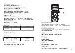
Press the
TEST
button to apply the test voltage. This button can
be turned clockwise while pressed to latch it. Allow several
seconds for the reading to stabilise. The test voltage is shown in
the lower-right corner of the display.
Note:
On completion of an insulation test, the
TEST
button, if
latched has to be manually released to discharge the circuit under
test. In the interest of safety the user should be aware of this.
If
OL
is displayed this means that the resistance being measured
is greater than the measuring range of the tester.
When a low resistance is measured, the test voltage drops; if it
drops to lower than 80V, a blinking indication of
0000
is displayed.
The buzzer can be toggled off and on by pressing the
)))
key.
INSULATION RESISTANCE ADVANCED FUNCTIONS
PI
(Polarization Index) key
Definition of PI
The polarization index is the ratio of the insulation resistance
measured after one minute and ten minutes. For good insulation,
the insulation resistance increases with time as the capacitive
leakage current and absorption current decrease. The higher the
PI value, the better the insulation. The quality of the insulation is
excellent for a PI that is greater than 4.0, good for 3.0 - 4.0, fair for
2.0 - 2.9, suspect for 1.5 - 1.9, poor for 1.0 - 1.4, and dangerous
for less than 1.0.
Setting Lower Limit
After exiting the Upper Limit set up, the Lower Limit set up is
automatically entered. The display shows
0000
, (if the lower limit
has been changed previously another number may be displayed)
with the right hand digit blinking.
LIMIT
and a downward triangle
also blink in the middle-right, and lower-left, respectively on the
display. Use
and
to select the digit to be changed, and
increase or decrease the value with
and
. After adjusting the
value, press
YES
to set the Lower Limit or
CANCEL
to discard the
changes, and exit Set Up.
8
13


