


Service manual
5 of 15
P3 PowerPort 1000 IP Install - Revision A, 10-26-2017
5 of 15
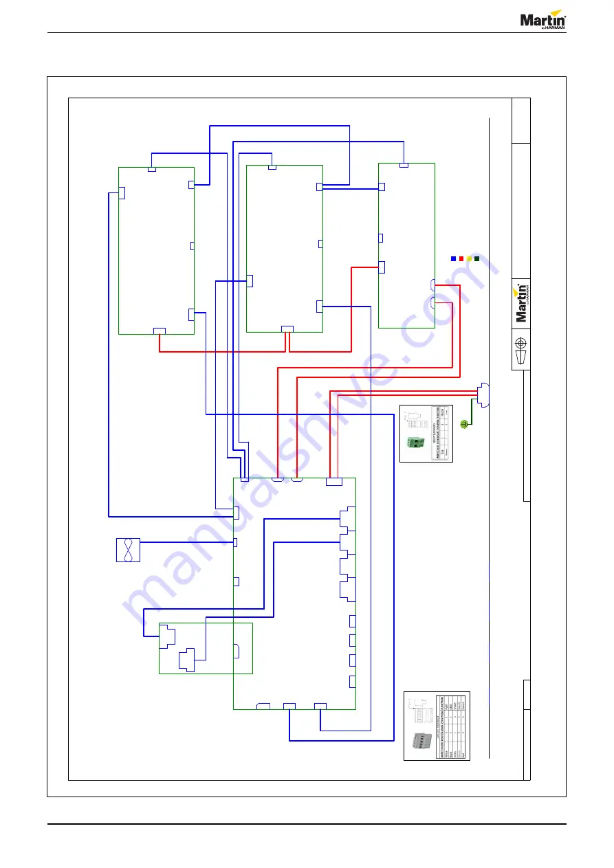
Wiring diagram
© 2017 Martin Professional
ApS
Martin™ General
Technical Specification apply to this item
Confidential
Page 1 of 1
P3 PowerPort 1000 IP
Install
1
A
A
N
o
t us
e
d
N
ot
m
ou
n
ted
N
ot
m
ou
n
ted
unshi
eld
Class 1 (High Voltage
Circuit)
Class 2 Wire
Harness
Mains Earth
Wire
Legend:
Isolated
Circuit
N
ot
u
s
ed
1
6
AW
G
mi
n
.
11862105
11862106
11862105
11862105
11862108
11862108
11851047
11862104
11862101
11862102
11862101
11862102
Wir
e on fan
11851048
11862110
unshi
eld
1
2
3
4
5
450V
_1
4
50V
_2
450V
_3
48V
_2
48V
_4a
48V
_4b
48V
_3
24V
_2
T
em
p_4
T
em
p_1
T
em
p_3
T
em
p_2
24V
_3
24V
_4
E
N
_1
E
N
_2
E
N
_3
11862110
P
L2,
P
L3,
P
L4,
P
L5:
P
L1:
PL
1
N
eu
tr
al
PL
1
DMX
2
P
L10
E
the
rne
t
PL
6
AUX
Po
we
r
2
PL
8
Tem
p.
3
PL
4
24V
4
P
L13
2x
24V
4
P
L18
C
on
tr
ol
ler
boar
d
120
P
FC
900W
62112004
PL
9
E
the
rne
t
P
L11
L
ine
O
ut
PL
5
48V
2
X4
<
F
unc
ti
o
n>
PL
4
24V
4
PL
8
Tem
p.
3
PL
4
VMX
5
PL
3
Po
we
r i
n
6
PL
2
E
n
abl
e
4
P
L19
48V
2
PL
2
E
n
abl
e
4
PL
7
450V
D
C
4
C
on
tr
ol
ler
boar
d
62050046
P
L20
48V
2
PL
1
DMX
2
P
L15
K
ey
/LE
D
Foi
l
16
PL
2
VMX
5
P
ow
er
c
on
M
ai
n
s
i
n
(
110-
230V
A
C
)
PL
8
E
the
rne
t
PL
5
48V
2
PL
5
Tem
p.
3
X5
<
F
unc
ti
o
n>
Tr
an
s
c
ei
ver
boar
d
62111002
DCDC 9
0
0
W
62112005
PL
3
Po
we
r i
n
6
PL
2
L
ine
PL
4
E
n
abl
e
2
PL
5
VMX
5
P
L17
Tem
p.
S
en
s
or
6
F
AN1
05741905
PL
7
E
the
rne
t
P
L16
Fan
4
PL
6
S
af
et
y
Loop
2
PL
3
VMX
5
P
L12
N
e
ut
ra
l O
ut
PL
1
M
a
ins
I
n
2
DCDC 9
0
0
W
62112005
Figure 5: Wiring diagram, P3 PowerPort 1000 IP Install


