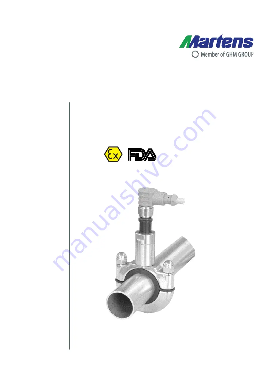
Operating Manual
Clamp-on Temperature Sensor
GTL720
EN
Save for later reference!
Page 1: ...Operating Manual Clamp on Temperature Sensor GTL720 EN Save for later reference...
Page 2: ...ical installation 6 3 1 Mechanical mounting 6 3 2 Mounting guidelines 6 3 3 Mounting notes 7 3 4 Instruction on Ordinance EC 1935 2004 7 3 5 Electrical installation 8 3 6 Connction diagram 8 4 Commiss...
Page 3: ...important to ensure that only electrically conductive thermal paste is used General safety instructions use These operating instructions must be kept where they are immediately available to specialis...
Page 4: ...nt of the operating instructions has been checked for compliance with the device described Deviations cannot however be excluded so that we offer no guarantee of full compliance The information in the...
Page 5: ...Figure 1 Block diagram 2 1 Delivery content Clamp on Sensor GTL720 Pipeline adapter RLA separate ordering position Silicone insert RLA included This operating manual GTL720 included 2 2 Operating prin...
Page 6: ...of measurement system 2 4 Type plate The nameplate contains the most important identification data Connection diagram Manufacturer Type and article designation Technical data Serial number Figure 3 Ty...
Page 7: ...0 5 1 5 m s Ambient temperature 30 C Medium Water Mounting direction Acc to position 1 3 1 Mechanical mounting Table 2 Reference condition for step response Figure 5 Step response T90 in water withou...
Page 8: ...the nominal diameter of the silicone insert 2 Clean the exterior of the pipe before installation Be sure that no chips swarf or other particles are lodged between sensor and pipe because this would pr...
Page 9: ...area may lead to distorted measuring results 3 Ideal Good measuring result if no air bubbles form Minimum distance to pipe angle 15 cm 6 inches 4 Questionable Lost heat and too small a distance from...
Page 10: ...al compound 5 For RLAs in FS 4 the metal clamp must be grounded 3 6 Connection diagram View at the plugs Connection design 1 standard Connection design 2 customized 4 Commissioning Maintenance and Ser...
Page 11: ...th is possible in principle but not recommended due to the submergence which deviates from normal application The utilization data limits see technical specifications for the device must be considered...
Page 12: ...evaluative silver plate on the heating surface Placing the sensor by hand is not practicable 5 Faultfinding Fault Cause Remedy Device offers no signal Break of wire Check wiring Device offers wrong si...
Page 13: ...ction class IP67 in connection with mounted M12 plug only Response time accuracyt1 Date medium temperature 120 C without thermal com pound with thermal com pound Step response T90 10 s approx 3 s appr...
Page 14: ...n dimensions Figure 10 Dimensions GTL720 RLA Frame size Pipe mm B mm h mm SW mm 1 13 0 19 9 51 26 11 2 20 0 33 9 64 32 11 3 34 0 53 0 92 46 14 4a 60 3 75 9 133 68 14 4b 76 0 88 9 133 68 14 Table 7 Fra...
Page 15: ...clamp on adapter Clamp on temperature sensor 1 2 3 4 5 1 Design input GTL720 Pt100 Sensor with M12 round plug 2 Electrical connection 0 GTL720 Variation 1 standard 1 GTL720 Variation 2 customized 3 M...
Page 16: ...mm DN15 230 23 0mm DN20 254 25 4mm 1 269 26 9mm DN20 280 28 0mm DN25 290 29 0mm DN25 337 34 0 33 7mm DN32 DN25 350 35 0mm DN32 Frame Size 3 381 38 1mm 1 400 40 0mm DN40 410 41 0mm DN40 424 42 4mm DN32...
Page 17: ...ckaging The device must be stored under the ambient conditions specified in the technical data 8 1 Returns Legal regulations for the protection of the environment and our personnel require that return...
Page 18: ...pecified under 8 1 Returns and we will then take care of proper disposal 9 Service 9 1 Manufacturer In case of any question don t hesitate contacting us GHM Messtechnik GmbH GHM GROUP Martens Kiebitzh...
Page 19: ...Clamp on Sensor GTL720 BA_MA_GTL720_EN_V1 08 17 17 BA_MA_TC125_EN_V0 13 10 EU Declaration of conformity...