Marshall Electronics
V-R171X-IMD-HDSDI
High Definition LCD Monitor with In-Monitor Display
Operating Instructions
Page 1: ...Marshall Electronics V R171X IMD HDSDI High Definition LCD Monitor with In Monitor Display Operating Instructions...
Page 2: ...1 Blue Only Mode 11 Pixel to Pixel Mode 12 Aspect Ratio Settings 12 Curtain Color 13 COLOR CONFIGURATION SUBMENU 14 Ctemp Gamma 14 Red Green Blue Offset 14 Red Green Blue Offset 14 SYSTEM CONFIGURATIO...
Page 3: ...s Pixel to Pixel mode Blue Only mode and user definable function buttons The V R171X IMD HDSDI can also be used as a standalone display with HD SDI loop through Features 1920 x 1200 Full Resolution 17...
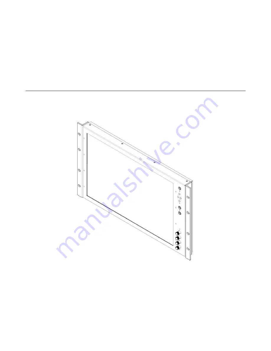
Page 4: ...on is required when installed to prevent possible damage to the monitor s internal components A VESA standard 75mm hole pattern also allows custom mounting installations Alternately the V R171X IMD HD...
Page 5: ...otoMenu Knob The RotoMenu knob is alternate means of accessing and navigating the main menu using only a single control Image Adjustment Knobs Use the image adjustment knobs to adjust color saturation...
Page 6: ...e monitor to the optional desktop stand See page 4 for details Tally Interface HD 15 Both LED tally and OSD tally can be activated via the HD 15 connector by connecting the corresponding pin to ground...
Page 7: ...Monochrome Save Defaults Back Save Mfg Load Config Mfg User 1 User 2 User 3 User 4 User 5 User 6 Save Config User 1 User 2 User 3 User 4 User 5 User 6 Main Board Main board firmware version number dis...
Page 8: ...menu or each submenu Press the SELECT button to enter a submenu or choose a setting Press the MENU button to exit the main menu or return to the main menu from a submenu Using the RotoMenu knob Press...
Page 9: ...s disabled when the aspect ratio is set to 4 3 or when Pixel to Pixel mode is enabled Note that in Full Screen mode markers are vertically stretched along with the picture to fit the 16 10 screen Off...
Page 10: ...afe Area 88 Safe Area 80 Safe Area 4 3 Marker Examples Marker Background Use this setting to choose how selected markers are displayed on the screen Off The marker is superimposed on the complete imag...
Page 11: ...r to SMPTE color bars with the following procedure 1 Allow the monitor to warm up for at least 5 10 minutes 2 Display SMPTE split field color bars on the monitor using an external source 3 Enable Mono...
Page 12: ...0 x 1200 IMD text and time code are superimposed on the lower portion of the image The audio presence indicator and on screen tally are displayed at the bottom of the screen outside the image In Scale...
Page 13: ...urtain Color Use this setting to choose the default color displayed on the screen when no video input is present Available colors are blue red green white and black IMD Text 00 00 00 00 00 00 00 00 IM...
Page 14: ...just the color temperature of the display Each setting adjusts the offset or brightness of each individual color component These settings will affect whichever color temperature preset is selected Red...
Page 15: ...panel of the monitor The following options are available for each button Marker Enable and rotate amongst marker settings choices depend on aspect ratio setting Center Marker Enable disable center mar...
Page 16: ...e loaded by selecting MFG Factory defaults cannot be overwritten Use the SAVE CONFIG menu to save the current settings to a preset from USR1 USR6 Save Defaults Use this setting to save the current val...
Page 17: ...aptive de interlacing algorithm Film cadence detection is disabled Motion adaptive interlacing uses a variety of real time algorithms to perform the best possible deinterlacing based on the content In...
Page 18: ...nt is ignored Film Indicator Use the Film Indicator setting to enable or disable the film mode detection icon If the Film Indicator is set to On a green square will appear in the top left corner of th...
Page 19: ...MD text commands see IMD Configuration Submenu for details page 22 Status Display Use this setting to enable or disable status display When enabled the current video input standard is displayed on the...
Page 20: ...e screen and green is shown at the bottom right GR Green tally is shown at the bottom left of the screen and red is shown at the bottom right The following diagrams show RGY RG and GR OSD Tally modes...
Page 21: ...ypes of time code can be selected to display on the screen LTC linear time code or VITC vertical interval time code The position of the time code display varies based on the aspect ratio setting and p...
Page 22: ...arshall Electronics for the latest protocol compatibility Image Video Use the Image Video protocol setting when controlling the IMD from an Image Video tally controller e g TSI 1000 or other controlli...
Page 23: ...ged and use the and buttons to scroll through character options Press ENTER to choose a character IMD Baud Rate Use this setting to choose the baud rate The baud rate must be set in conjunction with t...
Page 24: ...eo 422 setting to control Image Video tally states via the Image Video serial protocol LED and OSD tally will be disabled in this mode as Image Video tally states are manifested in the text color and...
Page 25: ...number of characters received by the UART Tx Total number of characters transmitted by the UART Serial Errors P Number of parity errors F Number of framing errors O Number of FIFO overrun errors Packe...
Page 26: ...TERFACE HD 15 Activation requires contact closure of pin to ground on the HD 15 connector Pin No Signal 1 Green 2 Red 3 Yellow 4 N C 5 Ground 6 N C 7 N C 8 N C 9 N C 10 N C 11 N C 12 N C 13 N C 14 N C...
Page 27: ...its original container for a period of one year from the purchase date This warranty is extended to the first consumer only and proof of purchase is necessary to honor the warranty If there is no proo...
Page 28: ...28 Marshall Electronics Inc 1910 East Maple Ave El Segundo CA 90245 Tel 800 800 6608 310 333 0606 Fax 310 333 0688 www LCDRacks com sales lcdracks com V2010 1216...