


0.6V or -0.6V
0V
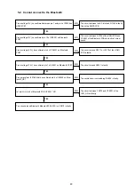
TROUBLE SHOOTING
1. POWER
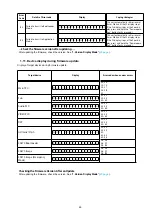
1.1. The unit does not power on
YES
YES
YES
NO
NO
YES
NO
NO
Does the power indicator on
the front panel flash in green
or white when the power is
turned on?
Has a fuse broken?
Does the power display
on the front panel change
to lighting in green after
approximately 10 seconds?
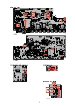
Check the voltage of pins
1,3-7 of N1019 on the HDMI
PCB while the power display
is flashing in green or white.
Remove the connector (CP4001) of the SPK PCB.
Check the "
3.5. Protection history display mode
"
)
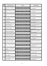
The unit does not power on
Has a fuse broken?
Does the power indicator on the
front panel flash in red when the
power is turned on?
Is DC5V being supplied from
the SMPS PCB (CN4141) to
the HDMI PCB?
See "
1.2.Fuse is blown.
"
See "
1.2.Fuse is blown.
"
Check the circuits around the Micropro-
cessor on the HDMI PCB and replace
any faulty parts.
TO "
3.5. Protection
History Display Mode
"
page
)
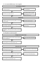
Are any parts not fully con-
nected in the connectors that
connect the PCBs?
Is DC5V output even when
the connector (N1029)
supplying power from the
SMPS PCB to the HDMI
PCB is removed?
Check the circuits around
the Microprocessor on the
HDMI PCB and replace any
faulty parts.
Check for breakages and short
circuits in the circuits and parts be-
tween N1029 on the HDMI PCB and
the microprocessor power supply
and replace any faulty parts.
Connect the connectors correct-
ly.
TO "
6. SMPS
"
(See
page
)
NO
YES
YES
YES
NO
NO
NO
YES
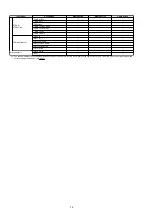
Check for leaks and short
circuits in the parts on the
primary side. Replace any
faulty parts.
Broken fuse
Check the rectifier diode in
the rectifier circuit on the
secondary side, and check
the circuit for short circuits.
Replace any faulty parts.
Replace the fuse after repair.
Check for short circuits between
the regulator output terminal and
GND in the power supply stabili-
zation circuit. Replace faulty parts
if there is a short circuit.
1.2. Fuse is blown
77
Summary of Contents for NR1605/FB
Page 8: ...Personal notes 8 ...
Page 26: ...Personal notes 26 ...
Page 103: ...CX870 7P 8P 5P PLATE PLATE 2P 7P 4P 7P 11P 5P 8P PLATE S30SC6MT WIRING DIAGRAM 103 ...
Page 140: ...Personal notes Personal notes 140 ...
Page 161: ...2 FL DISPLAY FLD 018BT021GINK FRONT U4400 PIN CONNECTION GRID ASSIGNMENT q T7 161 ...
Page 162: ...ANODE CONNECTION 162 ...


