background image

CAUTION

RISK OF ELECTRIC SHOCK

DO NOT OPEN

CAUTION: TO REDUCE THE RISK OF ELECTRIC SHOCK,

DO NOT REMOVE COVER (OR BACK)

NO USER-SERVICEABLE PARTS INSIDE

REFER SERVICING TO QUALIFIED SERVICE PERSONNEL

The lightning flash with arrowhead symbol, within
an equilateral triangle, is intended to alert the user
to the presence of uninsulated “dangerous voltage”
within the product’s enclosure that may be of suffi-
cient magnitude to constitute a risk of electric shock
to persons.

The exclamation point within an equilateral triangle
is intended to alert the user to the presence of
important operating and maintenance (servicing)
instructions in the literature accompanying the
appliance.

WARNING

TO REDUCE THE RISK OF FIRE OR ELECTRIC SHOCK,
DO NOT EXPOSE THIS APPLIANCE TO RAIN OR MOISTURE.

CAUTION:

TO PREVENT ELECTRIC SHOCK, MATCH WIDE BLADE

OF PLUG TO WIDE SLOT, FULLY INSERT.

ATTENTION:

POUR ÉVITER LES CHOCS ÉLECTRIQUES,

INTRODUIRE LA LAME LA PLUS LARGE DE LA FICHE DANS LA
BORNE CORRESPONDANTE DE LA PRISE ET POUSSER
JUSQU’AU FOND.

NOTE TO CATV SYSTEM INSTALLER:

This reminder is provided to call the CATV (Cable-TV) system installer’s attention to Article 820 – 40 of the NEC, that
provides guidelines for proper grounding and, in particular, specified that the cable ground shall be connected to the
grounding system of the building, as close to the point of cable entry as practical.

NOTE:

This equipment has been tested and found to comply
with the limits for a Class B digital device, pursuant to
Part 15 of the FCC Rules. These limits are designed to
provide reasonable protection against harmful interfer-
ence in a residential installation. This equipment gener-
ates, uses and can radiate radio frequency energy and, if
not installed and used in accordance with the instruc-
tions, may cause harmful interference to radio commu-
nications. However, there is no guarantee that interfer-
ence will not occur in a particular installation. If this
equipment does cause harmful interference to radio or
television reception, which can be determined by tuning
the equipment off and on, the user is encouraged to try 

to correct the interference by one or more of the follow-
ing measures:

– Reorient or relocate the receiving antenna.
– Increase the separation between the equipment and

receiver.

– Connect the equipment into an outlet on a circuit

different from that to which the receiver is connected.

– Consult the dealer or an experienced radio/TV techni-

cian for help.

NOTE:
Changes or modifications may cause this unit to fail to
comply with Part 15 of the FCC Rules and may void the
user’s authority to operate the equipment.

Summary of Contents for CR2020

Page 1: ...r grounding and in particular specified that the cable ground shall be connected to the grounding system of the building as close to the point of cable entry as practical NOTE This equipment has been...

Page 2: ...of power source indicated on the marking label If you are not sure of the type of power supply to your home consult your appliance dealer or local power company For video products intended to operate...

Page 3: ...rsonnel 20 Damage Requiring Service Unplug this video product from the wall outlet and refer servicing to qualified service personnel under the following conditions a When the power supply cord or plu...

Page 4: ...D BUS K version IN OUT IN L R OUT R SPEAKER SYSTEM 6 OHMS R L AUX ANNTENA FM 75 GND AM SYSTEM CD DIG OUT D BUS U version POWER EDIT CLOCK MEMO TUN PRESET PHONES MIN MAX VOL CD TUNER AMPLIFIER CR2020...

Page 5: ...be exposed to excessive heat cold moisture or dust it will not be exposed to direct sunlight it will not be exposed to electrostatic discharges Never place heavy objects on the equipment If a foreign...

Page 6: ...E OUT SYSTEM ANALOG D BUS IN OUT DIGITAL REMOTE EXT INT SYSTEM R 220V 110V VOLTAGE SELECTOR SD2020 MD2020 CR2020 CONNECTIONS Connection of D BUS Remote Control Bus This unit is equipped with the remot...

Page 7: ...ding time when making a tape recording 2 Main operation buttons PLAY PAUSE Starting play Interrupting play STOP Stopping play Erasing a program SKIP Fast search for a particular passage backwards to t...

Page 8: ...ntrol This knob adjusts the volume 6 Infrared sensor The infrared signal from the remote control enters the unit through this window When remote controlling the unit point the remote control transmitt...

Page 9: ...ng EDIT mode to enter the recording time when making a tape recording 4 TIME button Selecting the time information you want to see 5 CANCEL button Erasing track numbers you do not wish to include in a...

Page 10: ...s not going to be used for an extended period of time remove the batteries Also if you notice that the batteries are starting to run down replace them as soon as possible 1 Remove the battery cover 2...

Page 11: ...uency 2 While holding the MEMO button 3 depressed press the UP button 1 The auto preset memory operation starts Starts auto scanning within the band 3 The MEMO indicator flashes on the display 4 When...

Page 12: ...3 6 when the time of the day becomes 13 30 Now the clock starts To have the program timer function properly be sure to set the time of day beforehand To correct the time press the CLOCK button for th...

Page 13: ...ber of tracks on the disc and their total playing time are not displayed Caution in Timer Play A Be sure to set the present time before setting the timer operation B If the times set for two timer pro...

Page 14: ...t or the PLAY button on the remote control unit Playback pauses at the position where the button is pressed To resume playback press the PLAY PAUSE button on the set or the PLAY button on the remote c...

Page 15: ...ave been played the CD player exits from the edit play mode and enters stop mode By programming desired tracks before proceeding to edit playback the programmed tracks can be recorded automatically in...

Page 16: ...cording time Recording of the only one track can be easily done 1 In stop mode press the EDIT button to select MD EDIT This mode is activated when the blinking ends The MD is checked during the blinki...

Page 17: ...following checks you will be able to rectify a number of faults yourself without difficulty If the fault cannot be remedied after the following checks please consult your dealer or nearest Marantz se...

Page 18: ...Power output at 6 25 W T H D at 6 rated RMS output 0 06 Input sensitivity AUX TAPE MD 180 mV 47 k S N IHF A AUX TAPE MD 80 dB CD PLAYER SECTION Frequency range 20 Hz 20 kHz Dynamic range 85 dB S N 85...

Page 19: ...18...
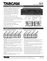
Page 20: ...EAKER SYSTEM 6 OHMS R L AUX ANNTENA FM 75 GND AM SYSTEM 220V 230V 115V CD DIG OUT D BUS FM EXTERNAL ANTENNA SPEAKER SYSTEM MD PLAYER K version only FM FEEDER ANTENNA AM LOOP ANTENNA AM EXTERNAL ANTENN...

Page 21: ...7 10 SG 281J851250 Manufactured under license from Dolby Laboratories Licensing Corporation Dolby the double D symbol and Pro Logic are trademarks of Dolby Laboratories Licensing Corporation is a regi...

Page 22: ...Model CR2020 User Guide MUSIC CONSOLE R CLASS 1 LASER PRODUCT LUOKAN 1 LASERLAITE KLASS 1 LASERAPPARAT...

Reviews: