background image

Operations Manual: OMI6900BP Series                                                                                                     14

Operations Manual: OMI6900BP Series                                                                                                     14

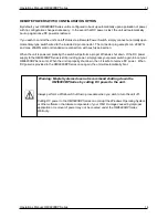
REMOTE POWER SWITCH CONFIGURATION OPTION

By default, your OMI6900BP Series unit is configured to boot up automatically upon application of power, 
with no configuration changes necessary.  In the event that DC power is lost, the unit will automatically 
boot up again once DC power is restored.

If you wish to control the unit’s on/off status via a Remote Power Switch, simply connect a normally open 
momentary-type switch wired to the included 2-pin connector. The connector plug accepts min. 28AWG 
and max. 20AWG solid or stranded wire connection, with push-type insertion.  

When the unit is powered, pressing the switch will perform a proper Windows shut down.  If the DC power 
supply to the OMI6900BP Series is still providing power, simply press your power switch again to boot your 
OMI6900BP Series unit.  When the unit is properly shut down, then it is safe to remove DC power.  When 
DC power is provided to the OMI6900BP Series once again, the unit will automatically boot.

Warning: Maple Systems does not recommend shutting down the  
                OMI6900BP Series by cutting DC power to the unit.  

Always perform a Windows Shut Down procedure when you wish to turn the unit off.  

Cutting DC power to the OMI6900BP Series can corrupt the Windows Operating System, 
or other software or hardware components of your OMI.  Damage caused by improper 
application or removal of power may not be covered under the OMI6900BP Series 
Warranty.  

Summary of Contents for OMI6900BP Series

Page 1: ...Source _____________________ www maplesystems com Maple Systems Inc 808 134th St SW Suite 120 Everett WA 98204 425 745 3229 OMI Operations Manual OMI6900BP Light Industrial Panel PC Series For use wi...

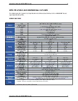
Page 2: ...ONS 8 OMI6915 DIMENSIONS 9 OMI6916 DIMENSIONS 10 OMI6918 DIMENSIONS 11 OMI6921 DIMENSIONS 12 I O PORTS 13 COM1 and COM2 13 LINE OUT 13 USB 13 LAN1 AND LAN2 13 REMOTE POWER SWITCH CONNECTOR 13 REMOTE P...

Page 3: ...229 Email support maplesystems com Web http www maplesystems com UNPACKING THE UNIT Carefully unpack the OMI6900BP Check all material in the container against the packing list Maple Systems will not a...

Page 4: ...tes uses and can radiate radio frequency energy and if not installed and used in accordance with the instruction manual it may cause interference to radio communications It has been tested and found t...

Page 5: ...for a more natural intuitive user touch experience compared to traditional analog resistive touch screen terminals Benefits of projected capacitive touchscreens include multi touch response pinch and...

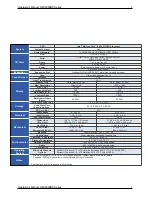
Page 6: ...olid State Drive Type 1 x 2 5 SATA 3 MLC Solid State Drive Capacity Options 64 128 256 512 GB SSD Storage SD Card Slot N A Input Voltage 9 36 VDC 9 36 VDC 9 36 VDC Input Current 1 31 5 22 A 1 14 4 56...

Page 7: ...tions 64 128 256 512 GB SSD Storage SD Card Slot N A Input Voltage 9 36 VDC 9 36 VDC Input Current 1 53 6 11 A 1 50 6 0 A Electrical Input Power max 55 W 54 W Dimensions W x H x D 19 67 x 12 39 x 2 57...

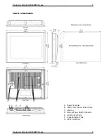
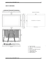
Page 8: ...0BP Series 8 Operations Manual OMI6900BP Series 8 OMI6912 DIMENSIONS A Power Connector B VESA 100 x 100 mm Screw Holes C Line Out D Remote Power Switch Connector E USB 3 0 Host Ports F Gigabit Etherne...

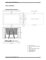
Page 9: ...0BP Series 9 Operations Manual OMI6900BP Series 9 OMI6915 DIMENSIONS A Power Connector B VESA 100 x 100 mm Screw Holes C Line Out D Remote Power Switch Connector E USB 3 0 Host Ports F Gigabit Etherne...

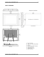
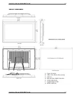
Page 10: ...BP Series 10 Operations Manual OMI6900BP Series 10 OMI6916 DIMENSIONS A Power Connector B VESA 100 x 100 mm Screw Holes C Line Out D Remote Power Switch Connector E USB 3 0 Host Ports F Gigabit Ethern...

Page 11: ...BP Series 11 Operations Manual OMI6900BP Series 11 OMI6918 DIMENSIONS A Power Connector B VESA 100 x 100 mm Screw Holes C Line Out D Remote Power Switch Connector E USB 3 0 Host Ports F Gigabit Ethern...

Page 12: ...BP Series 12 Operations Manual OMI6900BP Series 12 OMI6921 DIMENSIONS A Power Connector B VESA 100 x 100 mm Screw Holes C Line Out D Remote Power Switch Connector E USB 3 0 Host Ports F Gigabit Ethern...

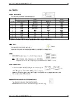
Page 13: ...r Type 3 5mm audio jack Line out HD Audio port can be connected to a speaker or headphones USB OMI6900BP models have 2 ea USB 3 0 type A ports Note USB 3 0 allows data transfers up to 5000 Mb s full s...

Page 14: ...ion When the unit is powered pressing the switch will perform a proper Windows shut down If the DC power supply to the OMI6900BP Series is still providing power simply press your power switch again to...

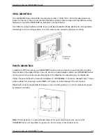
Page 15: ...mounting your OMI6900BP Series can be mounted in a panel using the mounting holes located on the sides and top of the unit Use the included clamps to fasten your OMI6900BP Series unit to a panel cut...

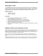
Page 16: ...le click the application setup exe file to begin driver installation Follow the instructional prompts on the screen We recommend that you restart your computer when prompted and after completion of al...

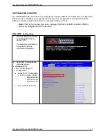
Page 17: ...IOS of your OMI6900BP can adversely impact the operation of your unit if incorrectly performed Maple Systems provides the below instructions solely for the operations specified and is not responsible...

Page 18: ...tructions on changing COM1 port mode Note COM1 is the only port that can be configured for RS422 or RS485 operation COM2 is exclusively configured for RS232 operation BIOS COM1 Configuration 1 Enter t...

Page 19: ...Included Apps Microsoft Edge Web Browser LibreOffice Suite Compatible with the following document types o MS Word o MS Excel o MS PowerPoint o Adobe PDF Media Player WONDERWARE AVEVA EDGE All the OMI...

Page 20: ...1010 1115 Rev 00 Maple Systems Inc 808 134th St SW Suite 120 Everett WA 98204 425 745 3229 Your Industrial Control Solutions Source _____________________ www maplesystems com...

Reviews: