151
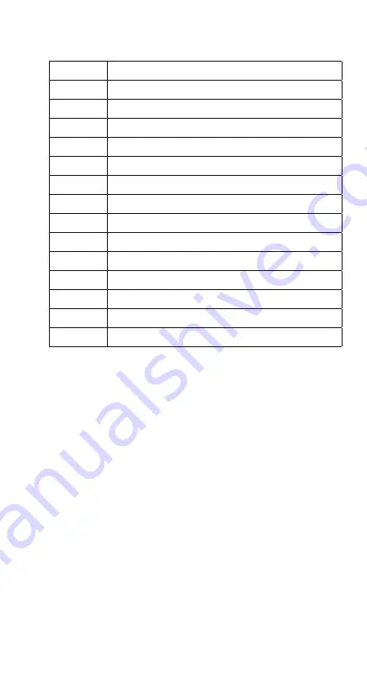
Tubing Diagram Legend
1
Compressor
2
Check Valve
3
Head Pressure Control Valve
4
Condenser (air or water cooled)
5
Receiver
6
Condensing unit Liquid Line Drier
7
Liquid Line Shut-off Valve
8
Ice Machine Liquid Line Drier
9
Liquid Line Solenoid Valve
10
Thermostatic Expansion Valve
11
Evaporator
12
S Trap (20’ + Rise Only)
13
Suction Line Shut-off Valve
14
Suction Line Filter
15
Suction Accumulator
Summary of Contents for RFF
Page 2: ......
Page 34: ...THIS PAGE INTENTIONALLY LEFT BLANK 34 Part Number 000015433_03 5 20 ...
Page 146: ...THIS PAGE INTENTIONALLY LEFT BLANK 146 Part Number 000015433_03 5 20 ...
Page 160: ...THIS PAGE INTENTIONALLY LEFT BLANK 160 Part Number 000015433_03 5 20 ...
Page 161: ......
Page 162: ......
Page 163: ......


