Manitowoc Grove GMK 5200-1 Maintenance Manual Download Page 83

Maintenance work on the carrier

7.3 Engine

0

9

.0

3.

201

8

Maintenance manual 

3 302 746 en

7 - 11

GMK5200-1 

 7.3            

Engine 

In addition, carry out the additional maintenance work as specified in the 

Engine manufacturer's documentation

 supplied with the vehicle. 

At the first oil change, fit a drain valve in place of the drain plug; 

à

p. 7 - 14

 7.3.1            

Checking the oil level 

Prerequisites 

– The truck crane must be level. 

Checking the oil 
level 

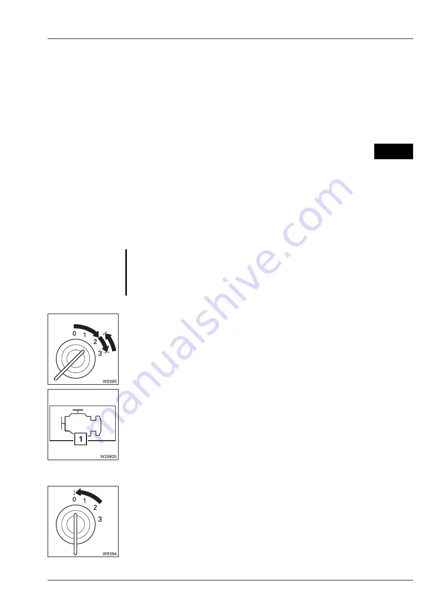
Start the engine from the driver's cab; 

à

Operating manual

Start the engine and watch the symbol (

1

). 

Stop the engine immediately

 if the symbol does not disappear after 

10 seconds. 
If symbol (

1

) is displayed, the oil pressure is too low. 

Allow the engine to run at idling speed for 2 - 3 minutes. 

Switch off the engine. 

Check the oil level after approx. 2 minutes. 

s

D

S

Risk of damage to the engine if the oil pressure is too low. 

Switch off the engine immediately if the symbol (

1

) is displayed. The engine 

can be damaged by running it when the oil pressure is too low. 

Summary of Contents for Grove GMK 5200-1

Page 1: ...Maintenance manual 3 302 746 en 09 03 2018 ...

Page 2: ...ent as well as the utilisation and disclosure of its contents is prohibited unless expressly permitted Infringement will incur liability for compensation All rights pertaining to registration of patent or utility model are reserved The original language of this document is German Important note Any type of duplication or excerpt from this document even in electronic form is not subject to the revi...

Page 3: ...nce overview 6 Lubricants and consumables 7 Maintenance work on the carrier 8 Maintenance work on the superstructure 9 Longer out of service periods 10 Torques 11 Spare parts required for maintenance Appendix This maintenance manual does not replace the operating manual Details of operation and standard safety instructions can be found in the operating instructions ...

Page 4: ...09 03 2018 3 302 746 en Maintenancemanual GMK5200 1 Blank page ...

Page 5: ...ons for using the maintenance manual 1 1 1 2 Warnings and symbols 1 1 1 3 Maintenance instructions 1 2 1 4 Instructions regarding the electronic control 1 4 1 5 Safety instructions for welding work 1 4 1 6 Definition of direction references 1 5 1 7 Conversion table for US measuring units 1 6 ...

Page 6: ...09 03 2018 3 302 746 en Maintenancemanual GMK5200 1 ...

Page 7: ...ting manual to highlight particularly important information The vertical line to the left of the text indicates that This text regardless of its length relates to the warning symbol s G This symbol indicates hazards related to the described operation and which may cause personal injury during execution The type of danger e g life threatening personal injury risk of crushing or electric shocks gene...

Page 8: ...pair work may only be carried out by a qualified repair crew e g Manitowoc Crane Care Repair work also requires Appropriate workshop equipment Special tools and Spare parts approved by Manitowoc Crane Group Germany GmbH It is your responsibility to maintain and service the truck crane regularly and carefully in order to extend its service life and keep it in good working order Please note that Man...

Page 9: ...y trained qualified personnel A few general maintenance instructions Clean the parts of the truck crane that are to be serviced particularly the area around the oil filler opening the oil inspection opening the oil drain opening and the lubricating nipples When changing the oil it should run out at operating temperature Ensure that only oils and lubricants specified in the Lubricants p 6 1 are use...

Page 10: ...1 4 Instructions regarding the electronic control The electronic ESX control is designed for a service life of 10 years In terms of use the control system s service life can be estimated based on the fol lowing limiting factors The service life of EEPROM allows 106 accesses The maximum number of make and break cycles for the safety relay is 107 Some conventional capacitors in the ESX have a servic...

Page 11: ...ans that Forwards always means with the driver s cab leading Backwards always means with the rear lights on the carrier leading On the superstructure The main boom head is always at the front which means that Switches and buttons For switches and buttons the terms down and up are used Regardless of the fitting position vertical horizontal diagonal perpendicu lar or turned the following always appl...

Page 12: ... of meas urement and vice versa Converting from into Multiply by mm in 0 03937 in mm 25 4 m ft 3 28084 ft m 0 30479 m ft 10 76391 cm in 0 155 cm in 0 061 l gal US 0 264178 kg lbs 2 204622 lbs kg 0 45359 t lbs 2204 622 lbs t 0 0004536 kN lbf 224 809 daN cm lbf in 14 50378 lbf in daN cm 0 06895 bar psi 14 50378 psi bar 0 06895 m s ft s 3 28084 km h or km mph or mi 0 62137 mph or mi km h or km 1 6093...

Page 13: ...ual 3 302 746 en GMK5200 1 2 Safety and environmental protection 2 1 Safety rules 2 1 2 1 1 Securing against unauthorised use 2 3 2 2 Handling substances which are harmful to the environment 2 4 2 3 Disposal of the truck crane 2 6 ...

Page 14: ...09 03 2018 3 302 746 en Maintenancemanual GMK5200 1 ...

Page 15: ...may be extended into horizontal position Do not carry out maintenance work unless the truck crane is standing on flat stable ground and is secured against rolling away Keep all handles steps railings and ladders free of dirt grease snow and ice Use the provided safe access aids and working platforms when carrying out work above body height Wear a safety harness when carrying out maintenance work a...

Page 16: ...n tenance work Escaping hydraulic fluid or compressed air can cause severe injury Remember that the hydraulic and compressed air systems of the truck crane are pressurised even when the crane is not in operation Tighten loose screw connections only when the systems are depressurised Always depressurise the hydraulic and compressed air systems before opening them Do not allow hot fluids to escape i...

Page 17: ...river s cab Locking the driver s cab and the crane cab Set up warning signs in the driver s cab and in the crane cab with infor mation about when why and by whom the truck crane was secured to prevent unauthorised use Remove the warning signs from the driver s cab and the crane cab after completion of the maintenance work G Danger due to unauthorised use Always stow away the hand held control in t...

Page 18: ...uctions in this chapter Using suitable equipment Substances harmful to the environment can sometimes be corrosive When doing maintenance work involving these consumables oils coolant fuel always use receptacles hoses pumps funnels etc which have sufficient capacity and which are resistant to the consumables For oil samples always use receptacles that can be closed and have suffi cient capacity and...

Page 19: ...es which are harmful to the environment keep solid materials e g filter cartridges separate from fluids Disposal costs will be reduced if you collect fluids separately according to defined categories Store environmentally harmful substances only in approved receptacles and in locations which meet the requirements of applicable national and regional regulations Disposal Ask your local environmental...

Page 20: ...er disposal Find out about the applicable official regulations regarding the final de registration and disposal at the place of registration of the truck crane At site find out about certified vehicle disposal companies Have the vehicle disposal company issue a disposal certificate for the truck crane Once collected have all the environmentally harmful substances dis posed of only by disposal comp...

Page 21: ...09 03 2018 3 Maintenance manual 3 302 746 en GMK5200 1 3 Cleaning 3 1 Overview of assemblies easily damaged when cleaning 3 2 ...

Page 22: ...09 03 2018 3 302 746 en Maintenancemanual GMK5200 1 ...

Page 23: ...nd switch boxes suction and ventilation filters or control elements and lubricated surfaces To prevent corrosion relubricate all slide faces after cleaning Keep all electric and hydraulic connections free of dirt Check the connect ing points for dust foreign bodies and moisture before installation This also applies to protective caps and bridging plugs The components specified in the next section ...

Page 24: ...Cleaning 3 1 Overview of assemblies easily damaged when cleaning 3 2 3 302 746 en Maintenancemanual GMK5200 1 09 03 2018 3 1 Overview of assemblies easily damaged when cleaning ...

Page 25: ... Lattice Extension 1 RCL terminal box 2 Telescopic slide faces 3 Pressure sensors on the derricking cylinder 4 Lowering limit switch 5 Suspension struts 6 Heating air conditioning system under the crane cab 7 Slewing angle sensor 8 Control units for outriggers 9 Angle data transmitter 10 RCL length data transmitter 11 Battery compartment 12 Spotlights pivoting 13 RCL connections 14 Lifting limit s...

Page 26: ...Cleaning 3 1 Overview of assemblies easily damaged when cleaning 3 4 3 302 746 en Maintenancemanual GMK5200 1 09 03 2018 Blank page ...

Page 27: ...09 03 2018 4 Maintenance manual 3 302 746 en GMK5200 1 4 Run in regulations ...

Page 28: ...09 03 2018 3 302 746 en Maintenancemanual GMK5200 1 ...

Page 29: ...itional equipment à Check V belt tension p 7 22 after50 30 Tighten the wheel nuts à Special torques p 10 2 after 150 95 Tighten the wheel nuts à Special torques p 10 2 after 50 Tighten the clips on the coolant hoses à Special torques p 10 2 after 100 Lubricate the outrigger beams à Lubricating the outrigger beams p 7 144 during the first 100 Check the hydraulic oil filter every week and change it ...

Page 30: ...er p 8 39 after 100 Tighten the bolts on the slewing bearing à Checking the screws p 8 21 à Special torques p 10 2 after 100 Hook blocks à Greasing p 8 71 after 200 First oil change on the hoists à Changing the oil checking the oil p 8 11 after 1000 or after 12 months at the latest Second oil change on the hoists à Changing the oil checking the oil p 8 11 after 200 Change the slewing gear oil à Ch...

Page 31: ...5 10 5 2 5 Maintenance plan M 6 5 12 5 2 6 Maintenance plan M 12 5 14 5 2 7 Maintenance plan Y 2 5 16 5 2 8 Maintenance plan Y 3 5 16 5 2 9 Maintenance plan Y 5 5 17 5 2 10 Maintenance plan Y 6 5 17 5 2 11 Maintenance plan Y 10 5 18 5 3 Periodic inspections 5 19 5 3 1 Load hook inspection 5 20 5 4 Measures required for winch monitoring 5 21 5 4 1 Theoretical service life 5 21 5 4 2 Proportion of t...

Page 32: ...09 03 2018 3 302 746 en Maintenancemanual GMK5200 1 ...

Page 33: ...ich the appro priate maintenance work is described The cross references consist of the chapter number and the corresponding page number e g Check hydraulic oil level à p 7 101 Checking the hydraulic oil level is described in chapter 7 the section starts on page 7 101 5 1 Maintenance intervals The length of the maintenance interval depends on the grade of oil used and operating conditions of the tr...

Page 34: ...nance plans Please note that the long term maintenance plans always include the short term ones Mainten ance plans Maintenance interval Driven km mi carrier Engineoperating hours oper hrs D daily before start ing up W weekly M 1 monthly approx 2 000 approx 1 240 approx 100 M 3 every three months 5 000 6 000 3 100 3 730 250 M 6 every six months 10 000 12 500 6 210 7 770 500 M 12 every 12 months 20 ...

Page 35: ...r better comprehension In addition to the Maintenance work on the carrier and the Maintenance work on the superstructure chapter 6 also lists the Lubricants and consum ables The designations of the oils lubricants in accordance with Lubricants list p 6 2 The amounts as approximate values for oil amounts in litres l and US gallons gal the exact oil amounts can always be determined by the oil level ...

Page 36: ... air filter à p 7 15 Checking the coolant level à p 7 16 Fuel system Draining off water from fuel filter 1 à p 7 28 Exhaust system with exhaust emission control Checking the AdBlue tank level à p 7 34 Wheels Checking the tyres for damage à p 7 73 Vehicle brake Checking the wear display à p 7 81 Steering Checking for leaks à p 7 95 Hydraulic system Checking the oil level à p 7 101 Electrical system...

Page 37: ... manual 3 302 746 en 5 5 GMK5200 1 D Maintenance work on the SUPERSTRUCTURE daily before putting into operation Hydraulic system Checking the oil level à p 8 31 Hoist ropes Checking the winding à p 8 53 Electrical system Checking the lighting and indicators à p 8 75 ...

Page 38: ...al inspection à p 7 49 Angle gear General inspection à p 7 54 Axle lines General inspection à p 7 61 Wheels Checking the tyre pressure à p 7 74 Compressed air system Draining water from the compressed air system à p 7 97 Checking for leaks à p 7 98 Hydraulic system Checking the hydraulic hoses à p 7 102 Checking for leaks à p 7 102 Central lubrication system Checking the level à p 7 119 Other main...

Page 39: ...p 8 10 Checking the hoist brake à p 8 10 Slewing gear Checking the oil level à p 8 15 Checking for leaks à p 8 16 Hydraulic system Checking the hydraulic hoses à p 8 32 Checking the ventilation filter à p 8 32 Checking for leaks à p 8 33 Hoist ropes Checking the hoist ropes à p 8 54 Central lubrication system Checking the level à p 8 69 Other maintenance work Checking the windscreen washing system...

Page 40: ...he oil level à p 7 54 Axle lines Axle centre drives checking the oil level à p 7 61 Final drives checking the oil level à p 7 67 Lubricating the cardan shafts in the axle lines à p 7 70 Wheels Checking that the wheel nuts are tight à p 7 75 Suspension Suspension struts checking the oil level à p 7 89 Suspension struts checking the fastening à p 7 91 Electrical system Checking the batteries à p 7 1...

Page 41: ...ntenance work on the SUPERSTRUCTURE monthly after approx 100 oper hrs Main boom Greasing the piston rod of the derricking cylinder à p 8 47 Air conditioning system Checking the air conditioning system à p 8 77 Cleaning the condenser fins à p 8 77 Other maintenance work Checking the auxiliary heater à p 8 82 ...

Page 42: ...sion Forced lever checking correct functioning à p 7 92 Hydraulic system Cleaning the magnetic rods à p 7 103 Electrical system Checking the charge level of the batteries à p 7 126 Charging the batteries using the battery charger à p 7 128 Check the external starting socket à p 7 129 Towbar coupling Checking the bearing à p 7 137 Checking the cotter pin à p 7 138 Checking the lower bushing à p 7 1...

Page 43: ...he SUPERSTRUCTURE every three months after 250 oper hrs Slewing bearing Checking the screws à p 8 21 Hydraulic system Cleaning the magnetic rods à p 8 34 Main boom Lubricating the telescopic sections à p 8 48 Checking the sheaves à p 8 52 Hoist ropes Lubricating the hoist rope à p 8 55 Hook blocks Checking the sheaves à p 8 71 ...

Page 44: ... months after 10 000 12 500 km 6 210 7 770 mi Engine Notes à Engine manufacturer s documentation à p 7 11 Transfer case Changing the oil à p 7 50 Angle gear Changing the oil and the oil filter à p 7 57 Axle lines Lubricating longitudinal cardan shafts à p 7 71 Wheels Changing the wheels à p 7 76 Air conditioning system Checking the entire air conditioning system à p 7 132 ...

Page 45: ...he SUPERSTRUCTURE every six months after 500 oper hrs Slewing gear Checking the slewing gear brake à p 8 16 Slewing bearing Lubricating the gear teeth à p 8 25 General inspection à p 8 27 Measuring tilting play à p 8 28 Cable drums Maintenance of the slip ring assemblies à p 8 67 Air conditioning system Checking hoses à p 8 78 ...

Page 46: ...ves changing the oil à p 7 63 Final drives changing the oil à p 7 68 Suspension Pressure accumulator checking the gas pressure à p 7 93 Steering Pressure accumulator checking the gas pressure à p 7 96 Compressed air system Replacing the filter cartridge of the compressed air drier à p 7 99 Hydraulic system Changing the ventilation filter à p 7 105 Taking oil samples depending on the oil sample tes...

Page 47: ...lter à p 8 36 Pressure accumulator checking the gas pressure à p 8 37 Taking oil samples depending on the oil sample test results Changing the hydraulic oil à p 8 37 à p 8 44 Changing the hydraulic oil filter à p 8 39 Main boom Checking the locking system à p 8 52 Hook blocks Greasing à p 8 71 Air conditioning system Checking the entire air conditioning system à p 8 78 Changing the pollen filter à...

Page 48: ...ging the oil and oil filter à p 7 24 Other maintenance work Having the fire extinguisher checked à p 7 149 Maintenance work on the SUPERSTRUCTURE every 24 months after 2 000 oper hrs Other maintenance work Having the fire extinguisher checked à p 8 88 Y 3 Maintenance work on the CARRIER every 36 months Transmission Changing the VIAB oil à p 7 43 Transmission oil change à p 7 46 Maintenance work on...

Page 49: ...towoc Crane Care or an authorised GROVE dealer Maintenance work on the SUPERSTRUCTURE every 60 months after 5 000 oper hrs Have both the cardan shafts resilient damper on the angle gear replaced by Manitowoc Crane Care or an authorised GROVE dealer Y 6 Maintenance work on the CARRIER every 72 months No maintenance work in this period The long term intervals always include the short term intervals ...

Page 50: ...e load bearing steel fabrication For further information please contact Manitowoc Crane Care Maintenance work on the SUPERSTRUCTURE every 120 months after 12 000 oper hrs Electrical system Have the battery on the electronics board replaced à p 8 76 Steel fabrication Check the load bearing steel fabrication For further information please contact Manitowoc Crane Care Rated capacity limiter RCL Have ...

Page 51: ...ections are generally visual inspections intended to assess the condition of the truck crane and its components Their purpose is to detect defects at an early stage and thus prevent accidents Inspections must be carried out on the following if they are not already included in the list of periodic maintenance work the hydraulic and electrical control and safety devices the rated capacity limiter RC...

Page 52: ...2 The original dimensions y y1 y2 are specified in field 2 on the load hooks To check this measure the distance between the marked measuring points on the load hook shaft 1 and the tip of the hook 3 The hook block may no longer be used if the opening has increased by more than 10 of its original dimension G Risk of accident through falling load Hook blocks with deformed load hooks are no longer sa...

Page 53: ...ations for Winches Hoists and Tractor Machines BGV D 6 VBG 9 and BGV D 8 VBG 8 5 4 1 Theoretical service life The theoretical service life is determined according to certain operating con ditions and a theoretical total operating time assumed by the design engi neer when calculating and dimensioning the winches of your truck crane The power unit group M3 and the load spectrum L1 Km 0 125 are gener...

Page 54: ...ctrum and the hoist operating hours must be determined for each inspection interval when determining the proportion of theoretical service life that has been used The operator is responsible for proper documentation in the crane logbook 1 Overloading caused by improper use of the truck crane 2 Insufficient maintenance Oil is not changed at the specified intervals 3 Operating errors Extreme acceler...

Page 55: ...e generally sub ject to only low stress 10 of the timing period with greatest load dead load 1 1 payload 40 of the timing period with dead load 1 3 payload 50 of the timing period with dead load only 0 125 Medium Q 2 L 2 Power units or parts thereof that are subject to high stress quite fre quently but which are generally subject to only low stress 1 6 of the timing period with greatest load dead ...

Page 56: ... the proportion of theoretical service life used Si is calculated using the formula This used proportion is subtracted from the remaining theoretical service life Di after every inspection interval see example in the appendix to this chapter If the remaining theoretical service life is not sufficient for the next operating period then a general overhaul of the winch must be performed If theoretica...

Page 57: ...rhaul under the following conditions The crane inspector has confirmed that the used proportion of the service life is correct and proper by signing his her name in the crane logbook after every expert inspection In this case the crane inspector must closely inspect the winch This includes at least A visual examination of the exterior for leaks damage deformation etc An oil inspection especially f...

Page 58: ... Load spectrum L 1 i e Km1 0 125 The operating hours counter for the main hoist reads 160 h i e T1 160 h The used proportion S1 of theoretical service life after the first inspection therefore is Remaining theoretical service life D1 3 200 h 160 h 3 040 h The above values are entered in the table see table example p 5 28 2nd inspection 2nd year The truck crane was used for unloading work on docks ...

Page 59: ...urs counter for the main hoist reads 940 h i e during this period 940 h 640 h 300 h T3 300 h The used proportion S3 of theoretical service life after the third inspection is therefore Remaining theoretical service life D3 1 120 h 600 h 520 h The values are entered in the table see table example p 5 28 The remaining theoretical service life is to be documented in a separate table for each winch Thi...

Page 60: ...e oper ating hours complete Superstruc ture operat ing hours Superstruc ture operat ing hours since the last inspec tion Winch oper ating hours Operating hours T i of the winch since the last inspection Used propor tion S i of the oretical service life D Remaining the oretical service life D i D i 1 S i Name of the expert Signature Comment Name of the approved inspector Signature i Km i h h h h h ...

Page 61: ...nts 6 1 6 1 1 Lubricants list 6 2 6 1 2 Lubricant applications list 6 3 6 2 Refrigerant 6 5 6 3 Consumables 6 5 6 3 1 Fuel 6 5 6 3 2 Engine coolant admixtures 6 5 6 3 3 After treatment of exhaust gases 6 6 6 3 4 Windscreen washing system admixtures 6 6 6 3 5 Fuel for crane cab heating system 6 6 ...

Page 62: ...09 03 2018 3 302 746 en Maintenancemanual GMK5200 1 ...

Page 63: ...ants and consumables 6 1 Lubricants All lubricants that you require for Maintenance work on the carrier p 7 1 and Maintenance work on the superstructure p 8 1 are listed with serial numbers in the lubricants list and the lubricant applica tions list à Lubricants list p 6 2 à Lubricant applications list p 6 3 ...

Page 64: ... 90 4 00552891 Gear oil C LPF MIL L 2105 B API GL 5 Hyp SAE 90 ISO VG 220 5 01373344 Gear oil MIL L 2105 C API GL 5 SHC 75 W 90 6 02310863 Gear oil Rivolta S K D 170 7 02313611 Gear oil C LPF MIL L 2105 B API GL 4 5 synthetic SAE 75 W 90 EP ISO VG 220 8 04162158 Hydraulic oil HVLP Castrol Hyspin AWH M 32 DIN 51524 3 ISO VG 32 9 03233369 Lubricating grease KP 1K 50 DIN 51825 Renolit JP 1619 50 C to...

Page 65: ...e for drive 10 x 8 à p 7 50 14 3 7 M 6 3er axle line axle centre drive à p 7 63 14 3 7 M 12 2nd axle line axle centre drive à p 7 63 13 0 3 5 M 12 5th axle line axle centre drive à p 7 63 13 0 3 5 M 12 4th axle line axle centre drive à p 7 63 16 5 4 4 M 12 6 or 8 x final drives à p 7 68 2 7 0 7 M 12 5 Gear oil Angle gear à p 7 57 7 7 2 0 M 6 6 Gear oil 5 x suspension struts à p 7 89 1 5 0 4 each M...

Page 66: ...1 Outrigger beams à p 7 144 M 1 Turntable lock à p 8 30 M 12 Hook blocks à p 8 71 M 12 Cab door hinges à p 7 145 M 12 Carrier pins à p 7 146 M 12 Superstructure pins à p 8 85 M 12 10 Spray Slewing bearing gear teeth à p 8 25 M 6 11 Slide paste Telescopic slide faces à p 8 48 M 3 12 Lubricating grease Telescope locking pins à p 8 48 M 3 Derricking cylinder piston rod à p 8 47 M 1 Cab door rails à p...

Page 67: ...f additives is not permitted and can cause damage to the engine system 6 3 2 Engine coolant admixtures The specifications and admixture ratios can be found in the Engine manufac turer s documentation Refrigerant Designation Usage Quantity to be filled in kg lbs Mainten_an ce interval Tetrafluoroethane R134a CAS no 811 97 2 EC no 212 377 0 Driver s cab air conditioning system à p 7 132 Compressor o...

Page 68: ...e truck crane is fitted with a separate tank for the auxiliary heater do you have the option of selecting whether to use the same fuel as in section 6 3 1 or to use EL heating oil Designation Usage Fillingquantity in litres gal DEF Diesel Exhaust Fluid 1 AdBlue GROVE part number 03140555 AdBlue tank on the carrier à p 7 34 40 10 5 1 DEF Diesel Exhaust Fluid Consumable for after treatment of exhaus...

Page 69: ...xhaust system with exhaust emission control 7 33 7 5 1 Checking the AdBlue tank level 7 34 7 5 2 Filling up with AdBlue 7 34 7 5 3 Check the exhaust system for external damage 7 35 7 5 4 Having the AdBlue system checked 7 37 7 6 Transmission 7 39 7 6 1 General inspection 7 40 7 6 2 Checking the VIAB oil level 7 41 7 6 3 Checking the transmission oil level 7 42 7 6 4 Changing the VIAB oil 7 43 7 6 ...

Page 70: ...r system 7 97 7 14 2 Checking for leaks 7 98 7 14 3 Replacing the filter cartridge of the compressed air drier 7 99 7 15 Hydraulic system 7 101 7 15 1 Checking the oil level 7 101 7 15 2 Checking the hydraulic hoses 7 102 7 15 3 Checking for leaks 7 102 7 15 4 Cleaning the magnetic rods 7 103 7 15 5 Changing the ventilation filter 7 105 7 15 6 Taking oil samples 7 106 7 15 7 Changing the hydraulic...

Page 71: ...5 Checking the initial tension of the springs 7 139 7 19 6 Checking the support ring 7 140 7 19 7 Checking the function of the coupling jaw resetting the central position 7 140 7 20 Other maintenance work 7 143 7 20 1 Checking the windscreen washing system 7 143 7 20 2 Lubricating the outrigger beams 7 144 7 20 3 Checking the auxiliary heater 7 145 7 20 4 Lubricating the cab door 7 145 7 20 5 Lubr...

Page 72: ...09 03 2018 3 302 746 en Maintenancemanual GMK5200 1 ...

Page 73: ... manual 3 302 746 en 7 1 GMK5200 1 7 Maintenance work on the carrier 7 1 General instructions 7 1 1 Covers Various types of work e g oil change require that the covers be removed Before maintenance work Remove the covers 1 After maintenance work Fasten the covers 1 with the locks ...

Page 74: ...Maintenance work on the carrier 7 1 General instructions 7 2 3 302 746 en Maintenancemanual GMK5200 1 09 03 2018 7 1 2 Overview of maintenance work on the carrier ...

Page 75: ...servoir à p 7 16 18 Oil filter à p 7 24 Fuel system à p 7 27 12 Left fuel tank à p 7 27 20 Right fuel tank à p 7 27 16 Filter 1 à p 7 28 17 Filter 2 à p 7 31 Exhaust system with exhaust emission control à p 7 33 13 AdBlue tank à p 7 34 15 Exhaust silencer with SCR catalytic converter à p 7 35 Transmission à p 7 39 6 VIAB oil level plug à p 7 41 7 Transmission oil level plug à p 7 42 8 Oil filter o...

Page 76: ...Maintenance work on the carrier 7 1 General instructions 7 4 3 302 746 en Maintenancemanual GMK5200 1 09 03 2018 ...

Page 77: ...system à p 7 97 10 Receptacle à p 7 97 14 Drier à p 7 99 Hydraulic system à p 7 101 1 Oil tank with inspection glass à p 7 101 2 Oil filters 1 and 2 à p 7 115 5 Oil filters 3 and 4 à p 7 115 3 Ventilation filter à p 7 105 4 Oil filler opening à p 7 111 Central lubrication system à p 7 119 15 Central lubrication pump à p 7 119 Air conditioning system à p 7 131 12 Air conditioning system in the driv...

Page 78: ...Maintenance work on the carrier 7 1 General instructions 7 6 3 302 746 en Maintenancemanual GMK5200 1 09 03 2018 ...

Page 79: ...er à p 7 95 5 Pressure accumulator à p 7 96 Electrical system à p 7 123 14 Carrier lighting à p 7 123 8 Battery box à p 7 124 7 External starting socket à p 7 129 Towbar coupling à p 7 135 15 Towbar coupling1 à p 7 135 Other maintenance work à p 7 143 13 Windscreen washing system receptacle à p 7 143 4 Outrigger beams à p 7 144 9 Cab door hinges à p 7 145 Driver s cab auxiliary heater1 à p 7 145 V...

Page 80: ...Maintenance work on the carrier 7 1 General instructions 7 8 3 302 746 en Maintenancemanual GMK5200 1 09 03 2018 Blank page ...

Page 81: ...ver s cab each day before starting work The Start menu shows the most important measurements and the Maintenance submenu shows all the outstanding warning messages à Operating manual Maintenance submenu If one of the symbols is displayed you must carry out the appropriate main tenance work Oil pressure à p 7 11 Coolant level à p 7 16 Air filter à p 7 15 Angle gear à p 7 54 Hydraulic oil filter à p...

Page 82: ...Maintenance work on the carrier 7 2 Symbols for maintenance work 7 10 3 302 746 en Maintenancemanual GMK5200 1 09 03 2018 Disc brakes wear display à p 7 81 ...

Page 83: ...ust be level Checking the oil level Start the engine from the driver s cab à Operating manual Start the engine and watch the symbol 1 Stop the engine immediately if the symbol does not disappear after 10 seconds If symbol 1 is displayed the oil pressure is too low Allow the engine to run at idling speed for 2 3 minutes Switch off the engine Check the oil level after approx 2 minutes s D S Risk of ...

Page 84: ... en Maintenancemanual GMK5200 1 09 03 2018 On the dipstick 1 check that the oil level is between the min and the max marks arrow markings Put the dipstick into the dipstick tube after checking the oil level If the oil level is too low Top up the oil à p 7 13 ...

Page 85: ...p Put the dipstick 1 into the dipstick tube after checking the oil level Engine oil in litres gal Designation to DIN 51502 Specification Classification GROVE part no 39 10 3 HD CD MIL L 2104 C DB 228 5 SAE 5 W 30 03329588 S Risk of damage to the engine if the oil level is too high Do not overfill the oil level must not be higher than the max mark arrow marking Drain off oil if necessary à Engine m...

Page 86: ...gainst unauthorised use à p 2 3 Installing the valve Check the thread size M 20 or M 26 Use a drain channel when draining the oil Drain the engine oil as described in the Engine manufacturer s documentation Fit a new gasket and tighten the valve 1 Check the valve for leaks after filling the oil For the next oil change you can drain the oil as done for the hydraulic tank à Handling the valves p 7 1...

Page 87: ... you must change the air filter Switch off the engine Spare parts and tools Prerequisites The engine must be switched off and secured against unauthorised use à p 2 3 Replacing the air filter Undo all the clamps 1 and remove the cover 2 Change the filters 3 and 4 Replace the cover and secure it with all the clamps D Designation Quantity GROVE part no Main filter 1 04161948 Back up filter 1 0416194...

Page 88: ...too low Top up the coolant Composition of the coolant à Engine man ufacturer s documentation Close the cap 1 D G There is a danger of scalding if the cooling circuit is hot The hot cooling circuit is under pressure When you open the expansion tank you could be scalded by escaping steam coolant Wear suitable protective gloves and cover the cap on the expansion tank with a rag before opening it Turn...

Page 89: ...g noises from the engine Check the engine and the connections for leaks If consumables are leaking à Checking the oil level p 7 11 à Checking the coolant level p 7 16 Check that pipes and hoses are tightly connected and not damaged If any damage is found report it to Manitowoc Crane Care or an authorised GROVE dealer or an authorised specialist workshop W ...

Page 90: ...e the radiator fins cleaned earlier than this Prerequisites The truck crane must be supported on outriggers and must be level à Operating manual The main boom must be fully retracted and raised to 75 à Operating manual The engine must be switched off and secured against unauthorised use à p 2 3 The working area on the carrier above the engine covers and between the radiator units must be freely ac...

Page 91: ...refrigerant for the driver s cab air conditioning system If necessary remove leaves twigs and other debris from the grilles 3 View the fan wheels 4 through the grilles from above to check their con dition The impeller blades must be clean and undamaged H If the radiator fins are heavily soiled have them cleaned since further soiling can lead to overheating à Have them cleaned p 7 20 G Risk of inju...

Page 92: ...ngers of your hand and amputate them Never reach into the fan wheels when they are rotating Do not push any tools through the grilles to clean them Always stop the engine before attempting to clean the fan wheels and radi ator fins S Risk of damaging the radiator fins Do not use a high pressure cleaner or steam jet cleaner The powerful jet may damage the fins Use only suitable cleaning agents air ...

Page 93: ... cleaned Have the cooling air baffle 5 cleaned Have the hoses and connections checked for damage and leaks Have any damaged parts replaced After checking cleaning Remove all tools and cleaning equipment Check that all the grilles 3 and plates 5 are secure Start the engine and wait until the fan wheels are rotating Check that the fan wheels are running freely Check the respective temperature displa...

Page 94: ...ntation Spare parts and tools Frequency measuring equipment GROVE parts no 04165439 new V belt frequency 102 8 Hz used V belt frequency 90 2 Hz Prerequisites The engine is not running and is secured against unauthorised use Checking Check the charge air cooling system 1 for dirt and damage Install a new V belt if required 1 Roughly set the initial tension with the tension tube 2 To do this loosen ...

Page 95: ... 1 it is ready for acoustic measurement Hold the measuring head 3 over the V belt 4 Hit the V belt 4 with an object tool so that it vibrates Read the measured value on the display 2 new V belt 102 8 Hz used V belt 90 2 Hz Correct the initial tension on the tension tube if required until the prescribed measure value has been achieved Check the tension on a newly installed V belt only after 4 operat...

Page 96: ...The engine must be switched off and secured against unauthorised use à p 2 3 Changing If a valve is already mounted on the oil pan Y 2 Engine oil in litres gal Designation to DIN 51502 Specification Classification GROVE part no 39 10 3 HD CD MIL L 2104 C DB 228 5 SAE 5 W 30 03329588 Designation Quantity GROVE part no Oil filter 1 04161614 Cover gasket 1 03328606 Gasket for oil drain plug 1 0416153...

Page 97: ... receptacle in place for the oil change Draining oil Remove the drain plug 1 or screw the con necting piece with hose on the valve 2 and drain the oil into the receptacle à Handling the valves p 7 112 If required you may replace the drain plug with a valve à p 7 14 Tighten the drain plug 1 torques for M 20 M 26 à p 7 14 or remove the connecting piece with hose from valve 2 and remove the receptacl...

Page 98: ...Maintenance work on the carrier 7 3 Engine 7 26 3 302 746 en Maintenancemanual GMK5200 1 09 03 2018 Blank page ...

Page 99: ...h may only be filled with a single type of fuel For additional equipment with a dual tank system the fuel tanks 1 and 2 are separate and are filled with different types of fuel à Operating manual Obtain information from Manitowoc Crane Care on the additional fuel filter required for the dual tank system The following elements are installed as standard in the carrier fuel line 1 Fuel filter 1 large...

Page 100: ... The engine must be switched off and secured against unauthorised use à p 2 3 Draining off water Place a receptacle underneath the filter Open the valve 1 If the consumable that emerges is clean close the valve by hand Remove the receptacle and properly dis pose of the drained consumable D O Risk of environmental damage due to leaking consumables Always let consumables drain into suitable receptac...

Page 101: ...switched off and secured against unauthorised use à p 2 3 If the fuel is contaminated Reduce the maintenance interval Changing Place a receptacle underneath the filter Open the valve 1 and let the consumable drain out s M 3 Designation Quantity GROVE part no Filter large 1 04161567 Alternatively Set of both filters 1 2 large small 1 04180966 O Risk of environmental damage due to leaking consumable...

Page 102: ...e the old filter 2 in the receptacle Insert a new filter 2 into the casing Attach the cover 1 torque 55 Nm 40 5 lbf ft à Engine manufacturer s docu mentation Remove the receptacle Open the two tank covers on the fuel tank à p 7 27 Operate the hand pump 1 until you sense definite resistance Close the two tank covers on the fuel tank Start the engine and check for leaks ...

Page 103: ... is contaminated Reduce the maintenance interval Changing Place a receptacle underneath the filter Remove the cover 1 Remove the old filter 2 from the casing Place the old filter 2 in the receptacle Insert a new filter 2 into the casing Attach the cover 1 torque 15 Nm 11 lbf ft à Engine manufacturer s documen tation Remove the receptacle s M 12 Designation Quantity GROVE part no Filter small 1 041...

Page 104: ... 7 32 3 302 746 en Maintenancemanual GMK5200 1 09 03 2018 Open the two tank covers on the fuel tank à p 7 27 Operate the hand pump 1 until you sense definite resistance Close the two tank covers on the fuel tank Start the engine and check for leaks ...

Page 105: ...tically sharply reduced when there is not enough AdBlue solution available Driving with an empty AdBlue tank will invalidate the truck crane s licence for use on public roads à Operating manual à Engine manufacturer s documentation AdBlue system 1 AdBlue tank 4 Pump unit for pumping AdBlue to the dosing unit on the diesel engine and for pumping engine coolant for preheating the AdBlue tank 2 Tank ...

Page 106: ...to carry additional can isters of AdBlue Start the engine and check the gauge after the engine starts à p 7 35 Refill with AdBlue before the tank becomes empty 7 5 2 Filling up with AdBlue Consumable and tools As required Two canisters of approx 20 l each 5 gal à p 2 4 Prerequisites A service station with a filling pump for AdBlue can be used or AdBlue can be filled manually from canisters The eng...

Page 107: ...damage Spare parts and tools Prerequisites The engine must be switched off and secured against unauthorised use à p 2 3 The engine and the exhaust system must be cool s G Danger of scalding due to ammonia vapours Ammonia vapour can escape if the AdBlue tank is opened when the outside temperature is high Ammonia vapours can irritate mucous membranes skin and eyes Ensure that there is adequate fresh...

Page 108: ...eck the filler neck for injecting AdBlue for external damage After checking Start the engine Check the AdBlue system gauge on the display in the driver s cab à p 7 34 Monitor if exhaust gases leak from possibly damaged places in the exhaust system Switch off the engine If you discover any damage Have any damaged parts of the exhaust system replaced immediately by Manitowoc Crane Care or an authori...

Page 109: ... for engine coolant for preheating the AdBlue tank Maintenance interval for the pump unit The engine manufacturer specifies additional maintenance intervals for the pump unit 1 à Engine manufacturer s documentation AdBlue filter Have the AdBlue filter in the pump unit 1 changed For the first time after one year M 12 after that every two years Y 2 Pressure accumulator Have the pressure accumulator ...

Page 110: ...ridge à Replacing the filter cartridge of the compressed air drier p 7 99 S Risk of damage to the pump unit Oil from the compressed air system can damage the pump unit Therefore a filter cartridge must be installed in the compressed air drier that removes both water and oil Manitowoc Crane Care recommends the suitable filter cartridge with the GROVE part number 04157844 ...

Page 111: ... VIAB 2 Transmission 3 VIAB VIAB is the abbreviation for Verschleißfreies Integriertes Anfahr und Bremssystem wear free integrated starting and braking system The VIAB is an oil filled clutch which permits starting and braking and delicate manoeuv ring Therefore the VIAB has its own oil supply and is filled with a special grade of oil à Checking the VIAB oil level p 7 41 s ...

Page 112: ... by the VIAB à Checking the transmission oil level p 7 42 7 6 1 General inspection Investigate any unusual running noises from the VIAB or transmission Check the transmission and the connections for leaks If consumables are leaking à Checking the VIAB oil level p 7 41 à Checking the transmission oil level p 7 42 Check that pipes and hoses are tightly connected and not damaged If any damage is foun...

Page 113: ...s or parked over an inspection pit The truck crane must not running and secured against unauthorised use à p 2 3 Checking the oil level Remove the drain plug 1 Check the oil level it must reach to the lower edge of the opening Fit a new gasket and tighten the drain plug If the oil level is too low Top up the oil à p 7 43 M 12 Designation Quantity GROVE part no Gasket 24 x 29 Cu DIN 7603 1 00117145...

Page 114: ...er an inspection pit The truck crane must not running and secured against unauthorised use à p 2 3 Checking the oil level Remove the drain plug 1 Check the oil level it must reach to the lower edge of the opening Replace the gasket and tighten the drain plug torque 25 Nm 18 4 lbf ft If the oil level is too low Top up the oil à p 7 48 M 12 Designation Quantity GROVE part no Gasket 24 x 29 Cu DIN 76...

Page 115: ...orised use à p 2 3 Draining oil s Y 3 Gear oil in litres gal Specification Classification GROVE part no 11 0 2 9 Shell Spirax S6 ATF VM 04162043 Designation Quantity GROVE part no Gasket 24 x 29 Cu DIN 7603 oil filler neck top 1 00117145 Gasket 24 x 29 Cu DIN 7603 oil level plug side 1 00117145 Gasket 24 x 29 Cu DIN 7603 oil drain cock bottom 1 00117145 Gasket 14 x 18 Cu DIN 7603 heat exchanger oi...

Page 116: ... gaskets and tighten the drain screw 1 to torque 24 Nm 17 7 lbf ft Changing the filter Remove the cover 1 Remove the old filter 2 from the casing Place the old filter 2 in the receptacle Insert a new filter 2 into the casing Replace the cover gasket and the vent valve Bolt the cover 1 on O Risk of environmental damage due to leaking consumables Always let consumables drain into suitable receptacle...

Page 117: ...oil through the hole 2 until oil comes out of the hole 1 Replace the gasket and tighten the drain plug 1 torque 55 Nm 40 5 lbf ft Replace the gasket and tighten the drain plug 2 torque 55 Nm 40 5 lbf ft Inspections after the oil change After changing oil check for leakage Start the engine and let it idle in neutral N Check the screw plugs 1 to 4 for leakage ...

Page 118: ...r oil in litres gal Specification Classification GROVE part no 17 5 4 6 with oil cooler Fuchs Titan Cytrac MB Synth API GL 4 SAE 75 W 90 04162042 Designation Quantity GROVE part no Filter 1 03328342 Spring 1 03328343 Gasket 1 03328344 Gasket 24 x 29 Cu DIN 7603 1 00117145 G Risk of scalding from gear oil at operating temperature You could burn yourself by gear oil escaping in an uncontrolled manne...

Page 119: ...Remove the connecting piece and hose from the valve 1 and take away the recep tacle Cleaning the filter Remove the drain plug 1 Take the strainer 2 and the spring 3 out and clean them Replace any damaged parts Insert the spring and strainer into the open ing Replace the gasket and tighten the drain plug torque 60 Nm 44 25 lbf ft s G Risk of injury due to spring tension The oil strainer bolt is spr...

Page 120: ...ole 2 until oil comes out of the hole 1 Replace the gasket and tighten the drain plug 1 torque 25 Nm 18 4 lbf ft Add an additional 1 5 l 0 4 gal oil through the hole 2 Attach the hose 2 Inspections after the oil change After changing oil check for leakage Start the engine and let it idle in neutral N Check the screw plugs 1 to 3 for leakage Check the hoses and connections on the oil cooler ...

Page 121: ...for leaks If consumables are leaking à Checking the oil level p 7 49 Check that pipes and hoses are tightly connected and not damaged If any damage is found report it to Manitowoc Crane Care or an authorised GROVE dealer or an authorised specialist workshop 7 7 2 Checking the oil level Spare parts and tools Prerequisites The truck crane must be raised on outriggers or parked over an inspection pit...

Page 122: ...ols Receptacle approx 15 l 4 0 gal à p 2 4 Prerequisites The truck crane must be raised on outriggers or parked over an inspection pit The engine must be switched off and secured against unauthorised use à p 2 3 M 6 Gear oil in litres gal Designation to DIN 51502 Specification Classification GROVE part no 12 8 3 4 for 10 x 6 x 10 14 0 3 7 for 10 x 8 x 10 C LPF MIL L 2105 B API GL 5 Viscosity Hyp S...

Page 123: ...itch the engine off and wait for approx 5 minutes Check the oil level à p 7 49 Check drain plugs 1 and 2 for leaks G Risk of scalding from gear oil at operating temperature You could burn yourself by gear oil escaping in an uncontrolled manner at operating temperature Wear appropriate protective gloves and take care not to come into contact with the gear oil O Risk of environmental damage due to l...

Page 124: ...Maintenance work on the carrier 7 7 Transfer case 7 52 3 302 746 en Maintenancemanual GMK5200 1 09 03 2018 Blank page ...

Page 125: ...r frame at the centre of rotation of the turntable Within the oil circuit 2 the gear oil for the angle gear 1 is routed under the chassis via a separate oil cooler 3 and through a separate filter 4 Access to the angle gear 1 is possible only when the truck crane is resting on outriggers the main boom is raised the turntable is turned to the 0 position to the rear the cover 2 at the centre of rotat...

Page 126: ... the oil level p 7 54 Check that pipes and hoses are tightly connected and not damaged If any damage is found report it to Manitowoc Crane Care or an authorised GROVE dealer or an authorised specialist workshop 7 8 2 Checking the oil level Symbols The oil is monitored by sensors in the angle gear and the following warning messages are displayed in the CCS menu Oil level too low Oil temperature too...

Page 127: ...g manual The engine must be switched off and secured against unauthorised use à p 2 3 The cover on the turntable over the centre of rotation must be removed The hydraulic drives and the angle gear must have cooled down suffi ciently The access opening and the interior space must be clean and free of oil so that the fitter can work safely in the restricted space where the angle gear is installed Ch...

Page 128: ...MK5200 1 09 03 2018 Checking the resilient dampers The angle gear is mounted on four resilient dampers Check the secure fastening and the condi tion of the resilient dampers 1 If the resilient dampers are damaged have them replaced by Manitowoc Crane Care or an authorised GROVE dealer ...

Page 129: ... to the 0 position to the rear à Operating manual The engine must be switched off and secured against unauthorised use à p 2 3 The cover on the turntable over the centre of rotation must be removed The hydraulic drives and the angle gear must have cooled down suffi ciently The access opening and the interior space must be clean and free of oil so that the fitter can work safely in the restricted s...

Page 130: ... valve is now locked in position Return the key to the storage location driver s cab or toolbox so that it is always available S Risk of damage to the angle gear If the drain tap remains open after changing the oil the oil circuit will be interrupted and the upper bearing will not be adequately supplied with oil This can lead to malfunctions and transmission damage The drain tap must always remain...

Page 131: ...he oil to drain from it Change the filter 6 Replace the gasket 5 s G Risk of scalding from gear oil at operating temperature You could burn yourself by gear oil escaping in an uncontrolled manner at operating temperature Wear appropriate protective gloves and take care not to come into contact with the gear oil O Risk of environmental damage due to leaking consumables Always let consumables drain ...

Page 132: ...e open ing 1 Fit a new gasket and tighten the screw 1 Close the valve lever 2 at right angles to the line Inspections after the oil change In order to circulate the oil around the oil circuit you must try out operation of a hydraulic function on the superstructure for instance tilting the crane cab Switch the engine off and wait for approx 5 minutes Check the oil level à p 7 54 Check the angle gea...

Page 133: ...king the oil level p 7 67 Check that pipes and hoses are tightly connected and not damaged If any damage is found report it to Manitowoc Crane Care or an authorised GROVE dealer or an authorised specialist workshop 7 9 2 Axle centre drives checking the oil level Spare parts and tools 1 Additional equipment 3rd driven axle line Prerequisites The truck crane must be raised on outriggers or parked ov...

Page 134: ...ew gasket and tighten the drain plug If the oil level is too low Top up the oil à p 7 64 3rd axle line This axle centre drive is available only with the 10 x 8 x 10 drive and is flanged directly to the transfer case à Transfer case p 7 49 Remove the drain plug 1 Check that the oil reaches the lower edge of the opening Fit a new gasket and tighten the drain plug If the oil level is too low Top up t...

Page 135: ... equipment 3rd driven axle line Receptacle approx 20 l 5 0 gal à p 2 4 s M 12 Gear oil in litres gal Designation to DIN 51502 Specification Classification GROVE part no Axlelines2 5 each 13 0 3 5 Axle lines 3 14 3 7 Axle lines 4 16 5 4 4 C LPF MIL L 2105 B API GL 5 Viscosity Hyp SAE 90 ISO VG 220 00552891 for drive Designation Quantity GROVE part no 10 x 6 x 10 Gasket 30 x 36 Cu DIN 7603 3 0011715...

Page 136: ...Fit a new gasket and tighten the drain screw 1 3rd axle line This axle centre drive is available only with the 10 x 8 x 10 drive and is flanged directly to the transfer case à Transfer case p 7 49 Place a receptacle under the screw 2 Unscrew the screws 1 and 2 and allow the oil to drain off Fit a new gasket and tighten the drain screw 2 Fill the oil up to the lower edge of the open ing Fit a new g...

Page 137: ... the oil drain off Fit new gaskets and tighten screws 3 and 4 First add 1 5 l 0 4 gal oil through the hole 2 Add more oil through the hole 1 up to the lower edge of the hole 1 Fit new gaskets and tighten screws 1 and 2 S Risk of oil overheating When topping up the oil both openings must be opened so that both oil tanks are filled equally This prevents both oil tanks from being overfilled and thus ...

Page 138: ...Maintenance work on the carrier 7 9 Axle lines 7 66 3 302 746 en Maintenancemanual GMK5200 1 09 03 2018 Blank page ...

Page 139: ...horised use à p 2 3 The parking brake must be released Checking the oil level Check the oil level at all other final drives in the same way Turn the wheel until the mark 2 is horizon tal and is on the right next to the centre of the axle Remove the drain plug 1 Check that the oil level is at the mark 2 Fit a new gasket and tighten the drain plug If the oil level is too low Top up the oil à p 7 69 ...

Page 140: ... must be released M 12 Gear oil in litres gal Designation to DIN 51502 Specification Classification GROVE part no for each final drive 2 7 0 7 C LPF MIL L 2105 B API GL 5 Viscosity Hyp SAE 90 ISO VG 220 00552891 for drive Designation Quantity GROVE part no 10 x 6 x 10 Gasket 24 x 29 Cu DIN 7603 6 00117145 10 x 8 x 101 Gasket 24 x 29 Cu DIN 7603 8 00117145 O Risk of environmental damage due to leak...

Page 141: ... same way Turn the wheel until the screw 1 is at the bottom Use a drain channel and place a receptacle under the screw Remove the screw and let the oil drain out Topping up the oil Turn the wheel until the mark 2 is horizon tal and is on the right next to the centre of the axle Top up the oil through the opening Fit a new gasket and tighten the drain screw 1 ...

Page 142: ...ngine must be switched off and secured against unauthorised use à p 2 3 The wheels must be turned as far as they will go so that the lubricating nipples on the sides of the final drives are more easily accessible Greasing Cardan shafts 2 are fitted only to the 10 x 8 x 10 drive Check which cardan shafts 1 and 2 have lubricating nipples 3 Clean the grease nipples 3 Inject grease into the grease nip...

Page 143: ...et Prerequisites The truck crane must be raised on outriggers or parked over an inspection pit The engine must be switched off and secured against unauthorised use à p 2 3 Greasing Check which cardan shafts 1 have grease nipples 2 Clean the grease nipples 2 Inject grease into the grease nipples until grease escapes from the bearing points Do not inject grease with excessive force otherwise the lip...

Page 144: ...Maintenance work on the carrier 7 9 Axle lines 7 72 3 302 746 en Maintenancemanual GMK5200 1 09 03 2018 Blank page ...

Page 145: ...eased Checking Check all tyres for Broken off tread blocks Dents Areas of uneven wear Whether the wear marking 1 has been reached Replace any damaged tyres If the tyres show varying degrees of wear change the wheels à Changing the wheels p 7 76 D S Risk of accidents due to uneven braking When replacing the tyres only use the same quality of tyres as those originally fitted dimensions load bearing ...

Page 146: ...ollowing table W S Risk of damage to the tyres The tyre pressure increases during operation Never release the increased air pressure of tyres at operating temperature Always check the tyre pressure in on road driving mode with cold tyres Tyres Air pressure of cold tyres in bar psi 14 00 R 25 385 95 R25 9 0 131 16 00 R 25 445 95 R25 9 0 131 20 50 R 25 525 80 R 25 7 0 102 ...

Page 147: ...e switched off and secured against unauthorised use à p 2 3 Checking the wheel nuts Check the wheel nuts and the pressure plates for damage Replace any damaged wheel nuts or pres sure plates Check the wheel nuts in sequence 1 12 for a tight fit torque 650 Nm 480 lbf ft M 1 Designation Quantity per wheel GROVE part no Wheel nut with pressure plate for steel rims 12 01207756 Wheel nut with pressure ...

Page 148: ...Only for two piece aluminium rims Have a specialist workshop check the bolts on the two piece aluminium rims using the appropriate special tool Depending on the manufacturer there are 20 or 22 bolts visible on the outer face of the rim On the inner face of the rim there are 20 or 22 nuts It is the torque of these that you must have checked in a specialist work shop à Recognising two piece aluminiu...

Page 149: ...s must be seated securely in the holes Around the edge of the aluminium rim there are impressed marks and safety instructions which must be complied with by the specialist workshop The nuts 1 are on the inner face of the rim The round heads must be free of cracks and securely seated on the bolts The torque must be checked within the specialist workshop s Aluminium rims with 20 nuts 550 Nm 406 lbf ...

Page 150: ...ance work on the carrier 7 10 Wheels 7 78 3 302 746 en Maintenancemanual GMK5200 1 09 03 2018 Mount the wheels on another axle as shown in the diagram Replace any damaged parts Tighten the wheel nuts à p 7 75 ...

Page 151: ... if the procedure is not carried out correctly This section only shows the sequence to be followed when changing wheels When removing mounting the wheels observe all the safety instructions and the procedure stated in the operating manual G Risk of accidents due to errors when mounting aluminium wheel rims Only have tyres fitted to aluminium wheel rims in an authorised workshop with the correct sp...

Page 152: ...Maintenance work on the carrier 7 10 Wheels 7 80 3 302 746 en Maintenancemanual GMK5200 1 09 03 2018 Blank page ...

Page 153: ...e lining thickness A is monitored by an electric wear indicator on the brake calliper 1 If the lining thickness A falls below the per missible minimum value a warning message is displayed on the on board computer in the driver s cab On the on board computer Familiarise yourself with the correct operation of the on board computer à Operating manual The Operation and Maintenance menu also provides i...

Page 154: ...s and tools Measuring tools for brake pad and brake disc thicknesses Dial gauge for the brake disc runout Ring spanner for adjustment Prerequisites The truck crane must be parked over an inspection pit The truck crane must be raised on outriggers The engine must be switched off and secured against unauthorised use à p 2 3 The wheels must be removed from all the axle lines The parking brake must be...

Page 155: ... all axle lines Measure the thickness Measure the thickness A of the brake discs 1 New brake discs have a thickness of 41 mm 1 61 in You must have the brake disc replaced if the thickness is less than 33 mm 1 30 in à Having the brakes repaired p 7 87 s G Risk of accidents due to incorrect work on the vehicle brakes Incorrect work on the vehicle brakes can lead to failure of the brakes caus ing sev...

Page 156: ...it values for damage A permissible B only permissible for a crack length up to three quarters of the length Y B only permissible for a crack width of up to 0 5 mm 0 02 in C only permissible for a depth of up to 1 5 mm 0 06 in D not permissible Measure the runout Attach the dial gauge 1 to the brake anchor plate 2 Position the measuring probe 3 perpen dicular to the brake disc 4 The distance A to t...

Page 157: ...n or oily à Having the brakes repaired p 7 87 Check that the electrical cable to the wear display is undamaged H The brake pad wear A is taken up by the automatic adjustment mecha nism When the pad thickness is small the travel adjustment is large and you must also check the adjustment mechanism à Checking the adjustment mechanism p 7 85 Checking the adjustment mechanism Using a ring spanner check...

Page 158: ...chanism is OK if the ring spanner turns one step anticlockwise at each brake application rotating a small angle at each step The adjustment mechanism is defective if the ring spanner fails to turn at any of the brake applications or turns only at the first brake application or at the brake application first turns anticlockwise but then turns back clockwise again If the adjustment mechanism is defe...

Page 159: ...e run in by periodic braking Perform a test drive to make sure that the new brake pads are sufficiently run in before putting the truck crane into normal operation G Risk of accidents due to uneven braking If the brake pads and brake discs are replaced on only one side of the axle then the wheels will brake unevenly Always have the brake pads and brake discs replaced on both sides of the axle Wher...

Page 160: ...Maintenance work on the carrier 7 11 Vehicle brake 7 88 3 302 746 en Maintenancemanual GMK5200 1 09 03 2018 Blank page ...

Page 161: ... 1 Oil in litres gal Designation GROVE part no 5 x suspension struts 1 1 5 0 4 each Gear oil Rivolta S K D 170 02310863 5 x suspension struts 2 3 2 0 84 each Designation Quantity GROVE part no Filter 1 03324588 S Risk of damage due to faulty suspension struts If the oil level is above the upper marking on the inspection glass the sus pension strut is faulty and must be replaced Notify Manitowoc Cr...

Page 162: ... oil collection tank All suspension struts 1 are connected to the oil collection tank 3 by a bleed hose 2 The oil collection tank 3 is accessible from below through the opening 4 Place an oil collection container under the oil drain plug 5 Open the drain plug 5 and allow the oil to drain normally this is a very small quantity If there is has been a large quantity of oil collected then one or more ...

Page 163: ...t Prerequisites The truck crane must be raised on outriggers à Operating manual The engine must be switched off and secured against unauthorised use à p 2 3 The wheels must have been removed Check whether the screws on all suspension struts are fitted tightly à Special torques p 10 2 M 1 1 on the upper bracket 2 on the lower bracket 3 on the lower flange 4 on the half shells for the steering arm 5...

Page 164: ...suspension à Operating manual Check whether all suspension struts are extended and the forced levers 1 are slackened If the suspension struts are not extended or only partially extended the forced lever is faulty Faulty forced levers should be replaced as soon as possible by Manitowoc Crane Care or an authorised GROVE dealer or your qualified repair crew M 3 G Risk of crushing when releasing the s...

Page 165: ...e suspension features integrated pressure accumulators that contain nitrogen 1 The filling pressure at 20 C 68 F is 50 bar 725 psi Have the filling pressure checked and if necessary corrected by Manitowoc Crane Care or an authorised GROVE dealer or an authorised specialist workshop M 12 G Risk of accidents due to incorrect inspection The gas pressure test must be carried out only by an authorised ...

Page 166: ...Maintenance work on the carrier 7 12 Suspension 7 94 3 302 746 en Maintenancemanual GMK5200 1 09 03 2018 Blank page ...

Page 167: ...essary à Checking the oil level p 7 101 After changing pipes and hose lines Bleed the hydraulic system à Bleeding the hydraulic system p 7 114 If damage cannot be rectified immediately or further damage is likely Notify Manitowoc Crane Care or an authorised GROVE dealer or your repair crew D G Risk of accidents from hydraulic oil spraying out Never tighten leaking connections when the system is un...

Page 168: ...g of the 4th and 5th axle lines The filling pressure at 20 C 68 F is 89 bar 1 290 psi Have the filling pressure checked and if necessary corrected by Manitowoc Crane Care or an authorised GROVE dealer or an authorised specialist workshop M 12 G Risk of accidents due to incorrect inspection The gas pressure test must be carried out only by an authorised official inspector of pressure tanks or under...

Page 169: ...on pit The compressed air supply is completely full à Operating manual The engine must be switched off and secured against unauthorised use à p 2 3 Draining water from the com pressed air system Actuate the valves 1 on the air reservoirs 2 to 9 If a great deal of moisture escapes Have the compressed air drier checked or replaced by Manitowoc Crane Care or an authorised GROVE dealer or your qualifi...

Page 170: ...s in the compressed air system connections pipes hose lines and valves If damage cannot be rectified immediately or further damage is likely Notify Manitowoc Crane Care or an authorised GROVE dealer or your repair crew W G Risk of accidents due to escaping compressed air Never tighten connections when the system is under pressure Only change gaskets pipes and hose lines when the system is depressu...

Page 171: ...ine must be switched off and secured against unauthorised use à p 2 3 Changing the filter cartridge Using the valve 1 release all the air from the reservoir 2 Replace the filter cartridge 3 using the strap wrench lubricate gasket slightly M 12 Designation Quantity GROVE part no Filter cartridge with gasket 1 04157844 G Risk of injury from escaping compressed air If the reservoir 2 is not completel...

Page 172: ...Maintenance work on the carrier 7 14 Compressed air system 7 100 3 302 746 en Maintenancemanual GMK5200 1 09 03 2018 Blank page ...

Page 173: ... unauthorised use à p 2 3 Check that oil is visible in the middle of the inspection glass 1 before starting work If the oil level is too low Top up the oil à p 7 113 O Risk of environmental damage due to leaking consumables Always let consumables drain into suitable receptacles Wipe up any con sumables that have leaked Store dispose of consumables and any soaked equipment properly Ask about the ap...

Page 174: ...he date of manufacture and the permitted operating pressure are marked on the hose fit ting Always ensure that the corresponding parts of the hydraulic system are depressurised Damaged or old hydraulic hoses must be replaced immediately 7 15 3 Checking for leaks When the engine is running carry out a visual inspection for leaks on the hydraulic system pumps drives cylinders control blocks valves p...

Page 175: ... must be standing on a level surface The engine must be switched off and secured against unauthorised use à p 2 3 During the first 100 operating hours Clean the magnetic rods weekly s G Risk of accidents from hydraulic oil spraying out Never tighten any leaking connections when the system is under pressure Change pipes and hose lines only when the system is depressurised O Risk of environmental da...

Page 176: ...agnetic rod 2 out of the filter cage 3 and clean it Replace any damaged parts where neces sary Assemble the filters 2 and insert them Replace the gaskets if necessary and fasten the cap 1 Start the engine and check for leaks S Risk of damage to the hydraulic system Large amounts of metal particles are a sign of damage in the hydraulic sys tem Have the hydraulic system checked by Manitowoc Crane Ca...

Page 177: ...change the ventilation filters earlier than normal Spare parts and tools Prerequisites The engine must be switched off and secured against unauthorised use à p 2 3 Remove the cover 1 Change the filter 2 and fasten the cover M 12 Designation Quantity GROVE part no Filter 1 03324588 O Risk of damage to the environment from filter residues Store used hydraulic oil filter inserts in suitable receptacl...

Page 178: ...tes The engine must be switched off and secured against unauthorised use à p 2 3 Select the sampling location To determine the usability of the oil you must take a sample from the hydraulic system To do that you must connect the hose with the connecting piece to a gauge port Remove the cover 3 The gauge port 1 is located on the cylin der 2 of the outrigger Clean the gauge port before connecting th...

Page 179: ...ing piece is dirty the dirt can contaminate the oil sample in the sample container during the sampling process The labo ratory analysis would thus be incorrect For flushing always allow 2 litres 0 5 gal of oil to flow through the hose into a receptacle before filling the sample container O Danger due to escaping hydraulic oil When you screw the connecting piece on to the gauge port the gauge port ...

Page 180: ...engine and put the hose end 2 into the sample container 5 Start the engine Allow 0 3 litres 0 08 gal of oil to flow into the sample container Switch off the engine Put the hose end back into the receptacle Seal the sample container Disconnecting the hose Disconnect the hose 2 the gauge port 1 closes Close the gauge port with the cap Allow the oil to flow out of the hose into the receptacle 3 Close...

Page 181: ...ory the viscosity the viscosity index the contamination the water content Determining the quality of the oil Compare the laboratory analysis with the limit values and carry out the specified measures if necessary Viscosity limit values Viscosity ISO VG 32 in accordance with DIN 51524 Part 2 Viscosity index Vi 150 If one of these limit values has been reached fallen short of Carry out an oil change...

Page 182: ...Maintenance work on the carrier 7 15 Hydraulic system 7 110 3 302 746 en Maintenancemanual GMK5200 1 09 03 2018 Blank page ...

Page 183: ... retracted à Operating manual The engine must be switched off and secured against unauthorised use à p 2 3 Close the valves Close the valves lever 1 at right angles to the line s Hydraulic oil in litres gal Designation to DIN 51502 Specification Classification GROVE part no 200 53 HVLP DIN 51524 3 Viscosity ISO VG 32 04162158 Castrol Hyspin AWH M 32 Designation Quantity GROVE part no Cover gasket ...

Page 184: ...eath the valves One after the other screw the connecting piece and hose onto the valves 1 and 2 à Handling the valves p 7 112 Change the filters à p 7 115 O Risk of environmental damage due to leaking consumables Use the supplied connecting piece and hose and a receptacle with sufficient capacity to drain the hydraulic oil G Danger due to escaping hydraulic oil When the connecting piece is screwed...

Page 185: ...he operating conditions After having changed the oil filters and topping up the oil you must re establish the operating conditions Opening the valves Open the valves lever 1 parallel with the line s S Risk of damage to the hydraulic system Cleanliness is of the utmost importance when handling hydraulic oil Even fresh hydraulic oil must be filtered before it is added to the tank S Risk of damage to...

Page 186: ...e raised on outriggers à Operating manual The parking brake must be engaged Bleed the steering cylinders individually one after the other Start the engine Bleed each steering cylinder 2 by loosen ing each of the collar nuts 1 in turn until the oil coming out no longer contains air bubbles If the steering system is still not operating properly Notify Manitowoc Crane Care or an author ised GROVE dea...

Page 187: ... indi cates that you must change oil filters 1 and 2 Filters 3 and 4 must be replaced after the first 50 hours in driving mode and then annually M 12 after this Spare parts and tools Receptacle approx 5 l 1 5 gal à p 2 4 Prerequisites The engine must be switched off and secured against unauthorised use à p 2 3 s Designation Quantity GROVE part no Filter for filters 1 and 2 Packing set 2 03329152 2...

Page 188: ...filter cage 4 Replace any damaged parts where neces sary Assemble the filters 2 and insert them Replace the gaskets and fasten the caps 1 Start the engine and check for leaks O Risk of environmental damage due to leaking consumables Store used hydraulic oil filter inserts in suitable receptacles and have them disposed of properly by qualified personnel S Risk of damage to the hydraulic system Larg...

Page 189: ...a receptacle Change the filter 2 Replace any defective parts where neces sary Fill the receptacle with clean oil Put the receptacle on and tighten it Change the filter on the opposite side in the same way O Risk of damage to the environment from filter residues Store used hydraulic oil filter inserts in suitable receptacles and have them disposed of properly by qualified personnel ...

Page 190: ...Maintenance work on the carrier 7 15 Hydraulic system 7 118 3 302 746 en Maintenancemanual GMK5200 1 09 03 2018 Blank page ...

Page 191: ...Filling pump from the tool set Prerequisites The parking brake must be engaged Checking the level Check the level in the grease container 1 The grease level must be near the max mark If it is below the min mark the level is too low If the level is too low Add more grease à p 7 120 s W Lubricating grease Designation to DIN 51502 Specification Classification GROVE part no Grease KP 1K 50 DIN 51825 0...

Page 192: ...iggered Fill the grease container up to the max mark Remove the filling pump wipe away any excess grease and close the holes S Risk of damage to the central lubrication system Cleanliness is of the utmost importance when handling grease and filling pumps Do not remove the caps from the opening and filling pump until immedi ately before refilling the grease This prevents dirt particles from getting...

Page 193: ... ing from the connection 2 no longer con tains any bubbles Bolt the cover 4 on Fasten the lubricating pipe at connection 2 Remove any grease that emerges 7 16 3 Triggering intermediate lubrication Intermediate lubrication should be activated after high pressure cleaning to check the lubrication system at all lubricating points Switch on the ignition Remove the cap 1 Press the button 2 for approx 2...

Page 194: ...Maintenance work on the carrier 7 16 Central lubrication system 7 122 3 302 746 en Maintenancemanual GMK5200 1 09 03 2018 Blank page ...

Page 195: ...ing light headlight marker lights rotating beacons fog tail light fog light outrigger lights Hazard warning system Brake lights Reversing lights Warning buzzer Reverse camera additional equipment Full beam headlight Turn signal indicators Windscreen wipers Windscreen washing system Horn Date time on CCS display D G Risk of accidents if the safety devices are faulty Have faulty lights and indicator...

Page 196: ...isk of explosion from escaping hydrogen Do not place tools on the battery and keep naked lights away from it G Risk of explosion from static charge Only use antistatic cloth to clean the batteries This prevents static charging which could result in hydrogen mixtures exploding G Risk of burns from battery acids Battery acid is highly caustic Wear safety glasses and protective gloves Do not tilt the...

Page 197: ... with a special battery terminal grease Checking the acid level Batteries without caps 1 are maintenance free Remove all caps 1 The acid level must be above the plates If the acid level is too low Top it up using only distilled water until the plates are covered Tightly bolt on all caps 1 After checking Push the battery box in Switch on the battery master switch 1 à Operating manual Check the time...

Page 198: ... battery contain lead Residue containing lead can stick to your hands and may not be allowed to enter your body e g by touching food Wash your hands after working on batteries G Risk of explosion from escaping hydrogen Do not place tools on the battery and keep naked lights away from it G Risk of explosion from static charge Only use antistatic cloth to clean the batteries This prevents static cha...

Page 199: ...t caps 1 are maintenance free Remove all caps 1 Read off the cell value on the acid siphon 2 and compare the value with that in the table à Charge level table p 7 126 Check all cells in the same way Tightly bolt on all caps 1 After checking Push the battery box in Switch on the battery master switch 1 à Operating manual Check the timers on the tachograph and on the auxiliary heater à Operating man...

Page 200: ...arate operating manual Connecting Take the battery charger out of its storage compartment in the driver s cab Insert the plug 1 into the socket 2 on the battery box Place the battery charger 3 in a protected place where you can see the indicator lamp 4 The battery charger can be suspended from the ring eyes 5 Insert the plug 6 into the socket on the mains supply 230 V at the location The indicator...

Page 201: ...itional equipment Consult the operating instructions supplied with the battery charger and regularly check that all components are functioning correctly to ensure that the external starting socket connecting cable and battery charger are ready for operation if needed à Operating manual Check the following Remove the cap 4 from the socket 1 Check that the cap is not damaged and is secured with the ...

Page 202: ...Maintenance work on the carrier 7 17 Electrical system 7 130 3 302 746 en Maintenancemanual GMK5200 1 09 03 2018 Blank page ...

Page 203: ...void further damage Have the air conditioning system repaired as soon as possible by Manitowoc Crane Care or an authorised GROVE dealer or an authorised specialist work shop 7 18 2 Checking hoses Check all refrigerant hoses for damage and areas of wear Have damaged hoses checked by Manitowoc Crane Care or an authorised GROVE dealer or an authorised specialist workshop only M 1 M 6 G Risk of burns ...

Page 204: ...per func tioning The inspection of the air conditioning system particularly includes the inspection of the refrigerant collector in accordance with the pressure container regulations test group II and the refrigerant compressor Only allow the system to be topped up with suitable refrigerant M 12 S Risk of damage to the condenser Do not use a high pressure cleaner or steam jet cleaner The powerful ...

Page 205: ...ance manual 3 302 746 en 7 133 GMK5200 1 Refrigerant Compressor oil FUCHS SE 55 Filler connections The filler connections 1 for refrigerants are on the refrigerant compressor hoses Fill quantity in kg lbs Designation CAS no EC no 1 0 2 2 Tetrafluoroethane R134a 811 97 2 212 377 0 ...

Page 206: ...conditions at extremely sandy or dusty loca tions you must change the filter earlier than normal Spare parts and tools Prerequisites The engine must be switched off and secured against unauthorised use à p 2 3 Changing Open the cover 1 Remove the filter 2 from the housing and clean the housing with a cloth Insert a new filter Fasten the cover M 12 Designation Quantity GROVE part no Filter 1 031349...

Page 207: ...al lubrication system Grease spare parts tools Grease gun from the tool set H To avoid over lubrication the towbar coupling may only be lubricated when open Clean the grease nipples 2 and 3 Open the towbar coupling To do this move the lever 1 up Press grease into the grease nipples 2 and 3 Close the towbar coupling s M 1 Lubricating grease Designation to DIN 51502 Specification Classification GROV...

Page 208: ...ection of the coupling jaw observe the arrow Remove any grease that emerges G Risk of injury when manually closing the towbar coupling When closing the lever moves down with great force in the direction of the coupling jaw Start the closing process only by moving the lever briefly in the direction of the coupling jaw with the ball of your hand If you hold the lever and move it down it may carry yo...

Page 209: ...pling by vigorously shaking it up and down and in the longitudinal direction arrows Hold the towbar coupling at the top and bottom of the coupling head and not by the coupling jaw The vertical play at the coupling head must be no more than 3 mm 0 1 in M 3 G Risk of injury Ensure that the towbar coupling is closed for the following work lever points downwards The lever may otherwise come down with ...

Page 210: ...the crowned section arrows must not be less than the following values If the dimension is smaller than that given above have the cotter pin replaced by Manitowoc Crane Care or an authorised GROVE dealer or your qualified repair personnel Also check the cotter pin for the correct ver tical play Take a screwdriver and press the pin 1 upwards The vertical play 2 of the pin must not exceed 4 mm 0 15 i...

Page 211: ...eed the following values If the dimension is larger than that given above have the bushing replaced by Manitowoc Crane Care or an authorised GROVE dealer or your specialist repair crew 7 19 5 Checking the initial tension of the springs The coupling head should require physical force to twist it when checking the torque Twist the coupling head clockwise and anticlockwise to check the initial tensio...

Page 212: ... When the trailer is coupled the draw eyelet of the trailer must not be in contact with the lower bushing 2 Have the support ring changed if The trailer s draw eyelet touches the lower bushing because of wear or The support ring has reached its wear limit of H 14 mm 0 55 in 7 19 7 Checking the function of the coupling jaw resetting the central position Spare parts and tool Torque wrench for torque...

Page 213: ...aw go The lever must automatically lock the coupling jaw in the middle position The coupling jaw is locked when the coupling can no longer move to the side H If the lever does not automatically engage with the coupling jaw the central position must be re adjusted à p 7 141 Resetting the middle position Open the coupling lever 1 pointing upwards and loosen the screws 2 Push the coupling jaw to the ...

Page 214: ...Maintenance work on the carrier 7 19 Towbar coupling 7 142 3 302 746 en Maintenancemanual GMK5200 1 09 03 2018 Blank page ...

Page 215: ... antifreeze to it A can for mixing and filling Topping up Open the cap 1 on the filler neck Top up the windscreen washing fluid through the filler neck Close the filler neck with the cap Wiping Press the multipurpose switch of the windscreen wiper washing system 6 and 7 à Operating manual Check all the wiping stages slow fast intermittent If the windscreen does not wipe clean Change the wiper blad...

Page 216: ...the outrigger cylinder and bearing surfaces on the outrigger pad by removing old grease dirt particles and rust Spray the uncovered end 2 making sure the grease coating is evenly distributed After every high pressure cleaning operation on the truck crane Lubricate the outrigger beams M 1 Lubricating grease Designation to DIN 51502 Specification Classification GROVE part no Grease KP 1K 50 DIN 5182...

Page 217: ...t to Manitowoc Crane Care or an authorised GROVE dealer or an authorised specialist workshop 7 20 4 Lubricating the cab door Grease tools Grease gun from the tool set Greasing Open the doors on the driver and passenger side Clean the grease nipples 1 on the door hinges Press grease into the grease nipples Close and open the doors several times the doors should move easily Remove any grease that em...

Page 218: ...d warning panels under the bumper Fastenings for the outrigger pads and socket pins on the outrigger Locks on the removable covers Hinges on the doors and covers of the storage box Check the pins for wear such as rust deformation broken clips chains and pin type keepers If the pins are damaged have them replaced by Manitowoc Crane Care or an authorised GROVE dealer or your qualified repair crew Us...

Page 219: ...ng At the factory the underside of the carrier was sprayed with corrosion pro tection for the first time The corrosion protection is solvent free and is water soluble while being sprayed on A transparent waxy protective film is formed after a drying time of one hour Check the condition of the original protective film If required remove any rust and touch up the paintwork before you spray on a new ...

Page 220: ...carrier using a spray exten sion Clean surfaces sprayed by accident immedi ately with water Let the corrosion protection dry for one hour Check that a transparent waxy protective film has covered the entire surface G Risk of injury to the eyes While working with the spray extension you could be hit by the spray jet or spray droplets Wear protective goggles protective clothing and gloves ...

Page 221: ...ctive national regulations and the operating location Ask the local fire safety officer about the national and local regulations Follow the operating manual 1 on the fire extinguisher Have the fire extinguisher serviced by trained personnel in good time before the maintenance interval specified on the label 2 expires Y 2 S Danger due to the fire extinguisher not working There is no guarantee that ...

Page 222: ...Maintenance work on the carrier 7 20 Other maintenance work 7 150 3 302 746 en Maintenancemanual GMK5200 1 09 03 2018 Blank page ...

Page 223: ...cating the gear teeth 8 25 8 5 3 General inspection 8 27 8 5 4 Measuring tilting play 8 28 8 5 5 Lubricating the locking of turntable 8 30 8 6 Hydraulic system 8 31 8 6 1 Checking the oil level 8 31 8 6 2 Checking the hydraulic hoses 8 32 8 6 3 Checking the ventilation filter 8 32 8 6 4 Checking for leaks 8 33 8 6 5 Cleaning the magnetic rods 8 34 8 6 6 Changing the ventilation filter 8 36 8 6 7 P...

Page 224: ...battery on the electronics board replaced 8 76 8 13 Air conditioning system 8 77 8 13 1 Checking the air conditioning system 8 77 8 13 2 Cleaning the condenser fins 8 77 8 13 3 Checking hoses 8 78 8 13 4 Checking the entire air conditioning system 8 78 8 13 5 Changing the pollen filter 8 80 8 14 Other maintenance work 8 81 8 14 1 Checking the windscreen washing system 8 81 8 14 2 Checking the auxi...

Page 225: ... manual 3 302 746 en 8 1 GMK5200 1 8 Maintenance work on the superstructure 8 1 General instructions 8 1 1 Covers Various types of work e g oil change require that the covers be removed Before maintenance work Remove the covers 1 After maintenance work Fasten the covers 1 with the locks ...

Page 226: ...Maintenance work on the superstructure 8 1 General instructions 8 2 3 302 746 en Maintenancemanual GMK5200 1 09 03 2018 8 1 2 Overview of maintenance work on the superstructure ...

Page 227: ... glasses à p 8 9 9 Hook block à p 8 71 7 Rope end fitting à p 8 54 3 Lowering limit switch à p 8 65 Slewing gear à p 8 15 6 Oil inspection glasses à p 8 15 Slewing bearing à p 8 21 10 Gear teeth à p 8 25 5 Slewing angle sensor à p 8 25 4 Locking of turntable à p 8 30 Hydraulic system à p 8 31 14 Oil tank with inspection glass à p 8 31 15 Oil filler opening à p 8 44 16 Ventilation filter à p 8 36 1...

Page 228: ...Maintenance work on the superstructure 8 1 General instructions 8 4 3 302 746 en Maintenancemanual GMK5200 1 09 03 2018 ...

Page 229: ...69 Electrical system à p 8 75 2 Spotlights on the crane cab à p 8 75 14 Spotlights on the telescopic boom à p 8 75 12 Anemometer air traffic control light à p 8 75 Air conditioning system à p 8 77 3 Crane cab air conditioning system à p 8 77 8 Condenser fins à p 8 77 5 Pollen filter à p 8 80 Other maintenance work à p 8 81 9 Windscreen washing system receptacle à p 8 81 Crane cab auxiliary heater1...

Page 230: ...Maintenance work on the superstructure 8 1 General instructions 8 6 3 302 746 en Maintenancemanual GMK5200 1 09 03 2018 Blank page ...

Page 231: ...ls every day before starting work CCS Check the symbols on the CCS start menu Crane Control System in the crane cab each day before starting work The Start menu shows the most important measurements and the Warn ing submenu shows all pending warning messages à Operating manual Warning submenu If a symbol is displayed you must carry out the maintenance work Hydraulic oil filter à p 8 39 ...

Page 232: ...Maintenance work on the superstructure 8 2 Symbols for maintenance work 8 8 3 302 746 en Maintenancemanual GMK5200 1 09 03 2018 Blank page ...

Page 233: ...against unauthorised use à p 2 3 Checking the oil level Check that the oil level is visible between the min and the max marks 1 If the oil level is too low Top up the oil à p 8 11 H The oil level in the hoist gear must be 16 mm below the centre of rotation of the hoist If the sight glass is loose in the clamps or a new sight glass has been fitted you must adjust this difference in height before yo...

Page 234: ... to Manitowoc Crane Care or an authorised GROVE dealer or your repair crew 8 3 3 Checking the hoist brake Check that the hoist brake is working correctly on the main hoist and the auxiliary hoist Attach the hook block to the hoist rope reeved once Lift a load of approx 9 5 t 21 000 lbs to approx 30 cm 1 0 ft above the ground Measure the distance to the ground when the load is hanging completely st...

Page 235: ...y and then eventually rises again to its true level s M 12 Gear oil in litres gal Designation to DIN 51502 Specification Classification GROVE part no 7 1 8 for each hoist C LPF MIL L 2105 B API GL 4 5 Viscosity SAE 75 W 90 EP ISO VG 220 02313611 Synthetic oil do not mix this with mineral based oils Designation Quantity GROVE part no Oil inspection glass complete 2 04161717 S Risk of damage to the ...

Page 236: ... the waste oil for abrasion particles or have it tested in a laboratory Pour the waste oil through a clean filter mat Examine the oil i e the residues on the filter mat using a magnifying glass If you find abrasion particles or solid materials on the mat the hoist gear must be dismantled and inspected by the manufacturer H Some abrasion particles may appear in the first oil filled If you notice su...

Page 237: ...he multiple disk brake and transmission unit and be permitted to exchange parts with signs of wear 8 3 6 Having a general inspection carried out H When carrying out the general inspection of the hoists also observe the information contained in Measures required for winch monitoring p 5 21 The general inspection involves removing the transmission and sending it to the manufacturer to be examined H ...

Page 238: ...Maintenance work on the superstructure 8 3 Hoists 8 14 3 302 746 en Maintenancemanual GMK5200 1 09 03 2018 Blank page ...

Page 239: ...el and in on road mode à Operating manual The engine must be switched off and secured against unauthorised use à p 2 3 Checking the oil level Always check the oil level prior to using the crane Check that oil is visible in the inspection glass 1 Always check the oil level for all the slewing gears If the oil level is too low Top up the oil à p 8 19 W Designation Quantity GROVE part no Gasket 10 x ...

Page 240: ...st be rigged for a slewing range of 360 according to the Lifting capacity table The RCL code for the current rigging mode must be entered à Operating manual The current load must not exceed 1 t 2 200 lbs where necessary unreeve the hook block The slewing range 360 around the truck crane must be secured The main boom must be raised to 45 and fully retracted W M 6 G Risk of overturning while slewing...

Page 241: ...ar is switched on Start the engine and switch on the slewing gear Open the CCS menu Hydraulic pressure Display 1 will show the pressure in the slewing gear s hydraulic circuit Move the control lever slowly to the stop and wait until the pressure in the hydraulic circuit has risen to approx 200 bar approx 2 900 psi If the superstructure still does not slew the braking force of the slew ing gear bra...

Page 242: ...4 Slewing gear 8 18 3 302 746 en Maintenancemanual GMK5200 1 09 03 2018 Switch the slewing gear off and switch the engine off Fasten the coil 1 to the valve Y 2304 using the nut Start the engine and check the slewing gear for correct operation ...

Page 243: ... the oil in all slewing gears s M 12 Gear oil in litres gal Designation to DIN 51502 Specification Classification GROVE part no 0 9 0 24 for each slewing gear C LPF MIL L 2105 B API GL 4 5 Viscosity SAE 75 W 90 EP ISO VG 220 02313611 Synthetic oil do not mix this with mineral based oils Designation Quantity GROVE part no Gasket 10 x 14 Cu DIN 7603 3 00117125 Gasket 14 x 20 Cu DIN 7603 3 00117132 O...

Page 244: ...neck 4 until oil is visible in the inspection glass 5 Replace the gaskets and tighten the screw 3 and the filter 4 Replace the plate 1 Checking the oil Check the waste oil that was drained from the slewing gears for abrasion particles or have it tested at a laboratory Pour the waste oil through a clean filter mat Examine the oil i e the residues on the filter mat using a magnifying glass If you fi...

Page 245: ...raised to 75 à Operating manual The current load must not exceed 1 t 2 200 lbs where necessary unreeve the hook block The slewing range 360 around the truck crane must be secured The engine must be switched off and secured against unauthorised use à p 2 3 Safety instructions s M 3 S Risk of damage to the screws on the slewing bearing All screws were tightened at the factory with a certain torque a...

Page 246: ...crews 1 Check all 95 screws 1 from below To do this you must rotate the turntable gradually with a pair of screws 1 each on the opposite side through the openings 2 in the carrier G Danger of the slewing bearing being ripped off If while checking you notice very loose broken or missing screws then the slewing bearing has been overloaded and is no longer safe to use During crane operation the slewi...

Page 247: ...crew head 1 is accessible only via a rectangular long narrow open ing 2 An extension 4 is required for fitting a socket wrench 3 A manual torque tool 5 is recommended so that it can be tightened gently and slipping from the screw head 1 is avoided Torques Screw type GROVE part number Torque Nm lbf ft Ball slewing bearing Bearing type KDV single row 04192540 or 03246884 Model plate Inside the inner...

Page 248: ...urntable by 180 the second group on the opposite side is now accessible Switch off the engine Check all other groups in the same way Checking the inner ring Divide the inspection of the 95 screws into 23 work steps with 4 screws each and 1 work step with 3 screws Between each of the 24 working steps you need to rotate the turntable to the next pair of screws on the opposite side Switch the engine ...

Page 249: ...st unauthorised use à p 2 3 Greasing Checking the slewing angle sensor Remove the plate 1 Check whether the pinion 2 is undamaged and lies straight and firmly against the gear teeth of the slewing bearing If need be remove dirt and foreign bodies from the pinion 2 If any damage is found report it to Manitowoc Crane Care or an authorised GROVE dealer Attach the plate s M 6 Designation Quantity GROV...

Page 250: ...from all the gear teeth 2 Apply a thin layer of new grease to all the gear teeth and allow it to penetrate for approx 10 minutes Apply a second thicker layer of grease and allow it to penetrate for approx 30 minutes Attach the plate Subsequent lubrication Remove the plate 1 Apply new grease to all the gear teeth 2 Allow it to penetrate for approx 30 minutes Attach the plate ...

Page 251: ...al noises occur take a sample of the grease that has escaped Have Manitowoc Crane Care examine the sample for metal residue Check the slewing bearing for damage e g gaskets If any damage is found report it to Manitowoc Crane Care or an authorised GROVE dealer or your repair crew H The maintenance interval specified here must be reduced if the slewing bearing was subjected to heavy blows falling lo...

Page 252: ...earing must have been previously checked for tightness à Checking the screws p 8 21 The truck crane must be rigged with an outrigger span of at least 8 95 x 7 80 m 29 4 x 25 6 ft and be aligned horizontally à Operating manual The counterweight combination of 7 0 t 15 400 lbs must be rigged according to the Lifting capacity table The lattice extension must be removed The auxiliary hoist must be rem...

Page 253: ...3 as close as possible to the gas ket 2 Slowly lower the main boom to 30 The hook block may not touch the ground Read off from the dial gauge how far the turntable is inclined and record this value as the current tilting play à Appendix Tilting play measurement report Remove the dial gauge Repeat the measurement with the slewing angles If the current tilting play is greater than the max permissibl...

Page 254: ...uck crane must be level and in on road mode à Operating manual The engine must be switched off and secured against unauthorised use à p 2 3 Greasing Familiarise yourself with the correct operation of the turntable lock à Operating manual Grease the lubrication points 1 with the brush M 12 Lubricating grease Designation to DIN 51502 Specification Classification GROVE part no Grease KP 1K 50 DIN 518...

Page 255: ...ff and secured against unauthorised use à p 2 3 Checking the oil level Check whether oil is visible in the middle of the inspection glass 1 If the oil level is too low Top up the oil à p 8 45 O Risk of environmental damage due to leaking consumables Always let consumables drain into suitable receptacles Wipe up any con sumables that have leaked Store dispose of consumables and any soaked equipment...

Page 256: ...emanual GMK5200 1 09 03 2018 8 6 2 Checking the hydraulic hoses The inspection work is described in section Checking the hydraulic hoses p 7 102 8 6 3 Checking the ventilation filter Check the display 1 on the ventilation filter If the indicator is coloured Replace the filter à p 8 36 W W ...

Page 257: ...changed Bleed the hydraulic system à Establishing the operating conditions p 8 46 If damage cannot be rectified immediately or further damage is likely Notify Manitowoc Crane Care or an authorised GROVE dealer or your repair crew W G Risk of accidents from hydraulic oil spraying out Never tighten any leaking connections when the system is under pressure Change pipes and hose lines only when the sy...

Page 258: ...must be switched off and secured against unauthorised use à p 2 3 During the first 100 operating hours clean the magnetic rod once a week M 3 Designation Quantity GROVE part no For oil filter 1 Filter 1 04156358 Packing set 1 04165792 O Risk of environmental damage due to leaking consumables Always let consumables drain into suitable receptacles Wipe up any con sumables that have leaked Store disp...

Page 259: ... Remove the filter 4 from the filter cage 5 Clean the filter cage 5 and the magnetic rod 3 Replace the filter 4 if necessary Assemble the filter 3 and insert it Replace the cover gasket if necessary Bolt the cap 2 on Fasten the cover 1 S Risk of damage to the hydraulic system Large amounts of metal particles are a sign of damage in the hydraulic sys tem Have the hydraulic system inspected by Manit...

Page 260: ...e switched off and secured against unauthorised use à p 2 3 Remove the cap 2 Change the filter 3 and fasten the cap Reset the display by depressing the pin 1 on the housing M 12 Designation Quantity GROVE part no Filter 1 03134932 O Risk of damage to the environment from filter residues Store used hydraulic oil filter inserts in suitable receptacles and have them disposed of properly by qualified ...

Page 261: ...e carrier hydraulic system Information for taking samples with the hose and for the laboratory analy sis à Taking oil samples p 7 106 Prerequisites The engine must be switched off and secured against unauthorised use à p 2 3 Select the sampling location To determine the usability of the oil you must take a sample from the hydraulic system To do that you must connect the hose with the connecting pi...

Page 262: ...the hose end 2 into the receptacle 4 Start the engine Tilt the crane cab Allow 2 litres 0 5 gal of oil to flow into the receptacle Switch off the engine and put the hose end 2 into the sample container 5 Start the engine Tilt the crane cab Allow 0 3 litres 0 08 gal of oil to flow into the sample container Switch off the engine Remove the hose à Disconnecting the hose p 7 108 Seal the sample contai...

Page 263: ...t be rigged with an outrigger span of at least 8 95 x 7 80 m 29 4 x 25 6 ft and be level à Operating manual The main boom must be fully retracted and raised to the maximum à Operating manual The engine must be switched off and secured against unauthorised use à p 2 3 s 1 Red Changing oil filter 1 2 Red Change oil filters 2 and 3 Designation Quantity GROVE part no For oil filter 1 Filter 1 04156358...

Page 264: ...ary Assemble the filter 3 and insert it Replace the cover gasket if necessary Bolt the cap 2 on Fasten the cover 1 O Risk of environmental damage due to leaking consumables Always let consumables drain into suitable receptacles Wipe up any con sumables that have leaked Store dispose of consumables and any soaked equipment properly Ask about the applicable regulations S Risk of damage to the hydrau...

Page 265: ...ge the filter 2 Replace the gaskets Fill the receptacle with clean oil and tighten it torque 25 Nm 18 4 lbf ft Changing oil filter 3 The oil filter 3 is located in the centre of rotation under the telescopic boom Remove the cover 3 Release the receptacle 1 at the hexagon Change the filter 2 Replace the gaskets Fill the receptacle with clean oil and tighten it up Fasten the cover 3 s ...

Page 266: ... valve if necessary à p 8 46 Check the oil level Top up the oil if necessary à p 8 45 To bleed the system start the engine and let it idle for 3 minutes Check that none of the oil filters is leaking S Risk of damage to the hydraulic pumps The engine may only be started if the valve in the suction line of the hydrau lic pumps is open and there is enough hydraulic oil in the hydraulic oil tank ...

Page 267: ...Maintenance work on the superstructure 8 6 Hydraulic system 09 03 2018 Maintenance manual 3 302 746 en 8 43 GMK5200 1 Blank page ...

Page 268: ... in on road mode à Operating manual The engine must be switched off and secured against unauthorised use à p 2 3 The oil filters must be removed à Changing the hydraulic oil filter p 8 39 Closing the valve Close the valve lever 1 at right angles to the line Hydraulic oil in litres gal Designation to DIN 51502 Specification Classification GROVE part no 980 259 HVLP DIN 51524 3 Viscosity ISO VG 32 0...

Page 269: ...ove the cap 1 and the filter 2 Add new oil via the filler neck 3 through a filter until the level reaches the centre of the inspection glass 4 Tighten the cap and filter s O Risk of environmental damage due to leaking consumables Use the supplied connecting piece and hose and a receptacle with sufficient capacity to drain the hydraulic oil S Risk of damage to the hydraulic system Cleanliness is of...

Page 270: ... conditions Opening the valve Open the valve lever 1 parallel to the line Start the engine Carry out all hydraulic functions several times to remove any air in the system Check that none of the oil filters is leaking Check the oil level through the inspection glass on the hydraulic oil tank Top up oil if necessary à p 8 45 S Risk of damage to the hydraulic pumps Open the valve prior to starting th...

Page 271: ...ressure cleaning operation on the truck crane Grease the piston rod H You can hinder the formation of rust if you turn the main boom to the side between maintenance intervals and completely lower it M 1 Designation GROVE part no Lubricant RHUS SW 2 1 kg Apply the grease with a brush 03325215 or Spray on Berulub 0 5 litres spray on 01929824 S Risk of damage to the derricking cylinder s gasket due t...

Page 272: ...ty tables necessary for maintenance à Lifting capacity table Section Telescoping sequences for greasing the boom The RCL code for the current rigging mode must be entered H If at the start you set up a rigging mode under which the telescope positions 50 100 0 0 0 are released in the context of the corresponding lifting capacity table this rigging mode allows you to perform the complete maintenance...

Page 273: ... Extend the telescopic section I to 100 Use a brush or a roller PAL1 to lubricate the outer upper and outer lower slide faces 3 Use the grease gun PAL1 to lubricate the upper inner slide faces at the lubricating nip ples 1 on both sides Use the grease gun RHUS SW 2 to lubri cate the locking pins at the lubricating nip ples 2 on both sides Lock and unlock the telescopic section I sev eral times so ...

Page 274: ... instructions regarding maintenance work The following diagrams show the lubrication of telescopic section V The telescopic sections IV III II are lubricated in the same way Extend telescopic section V to 100 and telescopic section IV to approx 25 Use a brush or a roller PAL1 to lubricate the outer upper and outer lower slide faces 3 Use the grease gun PAL1 to lubricate the upper inner slide faces...

Page 275: ... sides Raise the main boom to 15 Retract telescopic sections IV and V to 0 Fully extend and retract telescopic section V again so that the grease is distributed over the telescope slide faces Lower the main boom to 0 Lubricate telescopic sections IV III and II in the same way Before driving the truck crane Fully retracting all telescopic sections of the main boom after greasing may result in exces...

Page 276: ...ler or your repair crew 8 7 4 Checking the locking system Have the main boom locking system checked regularly by Manitowoc Crane Care or an authorised GROVE dealer M 3 M 12 G Risk of accidents if maintenance work is not carried out Have the maintenance work on the main boom locking system performed regularly by Manitowoc Crane Care or an authorised GROVE dealer This prevents the complete unlocking...

Page 277: ...check the entire length of the winding of the ropes 1 Slowly perform the lowering movement until the rope has moved over the complete width X of the rope drum The rope needs to be evenly wound The rope turns on the drum must be evenly spaced at a distance of 0 to 2 mm 0 to 0 08 in The cross over points must offset by approx 180 H The ropes of the top layer lie over the ropes of the bottom layer at...

Page 278: ...sing the condition of the hoist rope p 8 56 When 5 turns are left on the rope drum the lowering limit switch must switch off If the lowering limit switch does not switch off or switches off too late it must be reset à Setting the lowering limit switch p 8 65 Check the clamp 1 for damage and firm seating torque to 78 Nm 57 5 lbf ft The free end of the rope must not project above the flanged wheel T...

Page 279: ...ng brushing rolling or by running it through a tray filled with lubricant or by means of high pressure lubrication with a pressure pump H The Manitowoc Crane Group Germany GmbH recommends high pressure lubrication with a pressure pump GROVE part no 90018525 for reasons of sustainability efficiency and environmental protection When lubricating the hoist ropes observe the instructions concerning the...

Page 280: ...of the rope you must be familiar with the following The type of rope regular lay The number of load bearing wires in the outer strands The rope diameter à Operating manual In a regular lay rope 1 the wires run more or less in the longitudinal direction of the rope You get the number of load bearing outer wires 1 by counting the number of outer strands of the rope and multiplying by 7 H If there ar...

Page 281: ...n a rotation resistant hoist rope The rope section runs over a rope disc or on a drum wound as a single layer Number of load bearing outer wires 13 mm 16 mm 17 mm to 78 mm to 390 mm to 96 mm to 480 mm to 102 mm to 510 mm 101 120 3 5 3 5 3 5 121 140 3 5 3 5 3 5 19 mm 22 mm 24 mm to 114 mm to 570 mm to 132 mm to 660 mm to 144 mm to 720 mm 101 120 3 5 3 5 3 5 121 140 3 5 3 5 3 5 The rope section is r...

Page 282: ...are protruding from the rope General wear caused by ageing of the rope or consequential dam age as a result of dam age to the rope Replace the rope at the latest when the maximum permissi ble number of wire breaks according to the table are visible externally Replace the rope immediately if wire break clusters or strand breakages occur The frequency of wire breaks increases with a rope s age For r...

Page 283: ... Corkscrew type rope deformation 2 The rope winds its way along its longi tudinal axis in a way that is similar to a corkscrew Deformation is measured with sus pended hook block Damage resulting from overloading Even a small amount of defor mation leads to increased abrasion wire breaks and rough operation of the rope drive If deformation x at a position on the rope is greater than a third of the ...

Page 284: ...loose Only the inner strands continue to bear the load Corrosion or abra sion Replace the rope immediately Other causes The number of wire breaks determines when the rope must be replaced Knot forma tion 3 If there is repeatedly occurring knot like thickening of the rope the insert comes out fre quently Strands bear on each other at thin points increased frequency of wire breaks General wear due t...

Page 285: ...ving over the rope Determine number of wire breaks replace rope immedi ately if serious crushing has occurred Kinks 2 Rope deformation with twists and wire breaks Rope in the eyelets was pulled straight while twisted Replace the rope immediately Buckling 3 Buckled section in the rope Mechanical damage Replace the rope immediately Crinkling 4 Crinkling rope deformation Loaded rope was pulled over a...

Page 286: ...ng manual Replacing the old rope Unreel the hoist rope until it switches off Adjust the lowering limit switch so that you can unreel the rope com pletely à Setting the lowering limit switch p 8 65 Unreel the remaining layers from the hoist drum Protect the truck crane from unauthorised use à p 2 3 S Risk of accidents from falling load Use only a replacement rope that has the same technical specifi...

Page 287: ...ce life therefore Make sure the rope is not twisted when it is inserted Avoid soiling and damage when fitting Wind the rope up in the same direction in which the rope is reeled on to the reel Tense the rope slightly while winding it up Place the reel stand 1 with the new rope in front of the main boom head The distance X between the reel stand 1 and the head sheave 2 must be at least 30 m 100 ft s...

Page 288: ...t torque to 78 Nm 57 5 lbf ft Place the rope wedge 1 in the loop Push the rope back until the rope wedge 1 is fully in the pocket 2 Ensure that the rope wedge loop and rope end do not protrude beyond the flanged wheel This will prevent damage Start the engine Hold the rope taut and wind up the rope slowly Reeve a hook block reeve it at least 5 fold à Operating manual Raise the main boom to a steep...

Page 289: ...t and on the aux iliary hoist Spare parts and tools Prerequisites A hook block must be reeved 5 fold à Operating manual The main boom is fully raised and extended à Operating manual The hook block is lowered until only five turns of the rope remain on the hoist drum s G Risk of accidents if the lowering limit switch is set incorrectly After inserting a new rope the lowering limit switch must alway...

Page 290: ...g switch off Raise the hook block until there are approx 10 turns on the hoist drum Lower the hook block and check whether the lowering limit switch switches off properly The lowering limit switch must switch off the hoist while five rope turns are still on the hoist drum Correct the setting of the lowering limit switch if necessary G Risk of accidents if the rope end fitting is overloaded The low...

Page 291: ...ll counterweight plates must be removed the opening for cable drum 2 at the rear of the turntable must be accessible à Operating manual The main boom must be set down on the support à Operating manual The engine must be switched off and secured against unauthorised use à p 2 3 The ignition must be switched off in the driver s cab à Operating manual s 1 Cable drum 1 2 Cable drum 2 M 6 Designation Q...

Page 292: ...the cable drum S Risk of damage to the RCL Before maintenance work on the slip ring assemblies always switch off the battery master switch so that the cable drum is without power This prevents short circuits which may lead to damage to the rated capacity limiter RCL G Risk of crushing from movement of the main boom Only perform maintenance work when the main boom is resting in the sup port and the...

Page 293: ...GMK5200 1 8 10 Central lubrication system 8 10 1 Checking the level The maintenance of the pump 1 is similar to the maintenance on the carrier à Central lubrication system p 7 119 Connected lubricating points Main hoist drum Auxiliary hoist drum Slewing bearing Telescopic unit pivot pins Derricking cylinder pivot pins W ...

Page 294: ...Maintenance work on the superstructure 8 10 Central lubrication system 8 70 3 302 746 en Maintenancemanual GMK5200 1 09 03 2018 Blank page ...

Page 295: ...regulations p 4 1 Grease spare parts tools Grease gun from the tool set Prerequisites The hook block has been reeved at least twice à Operating manual Greasing On the hook blocks supplied the sheaves crossheads and load hooks of the axial bearings are greased H The sheaves on the hook block often have no grease nipple and are main tenance free Check all hook blocks for grease nipples Hook blocks w...

Page 296: ...200 1 can be equipped with hook blocks that can be separated The figure shows an example of the removable components on a hook block Separable hook block Check the separatable joints 1 for damage Check the bolts 2 and the retaining pins 3 for damage G Risk of accidents due to non secured hook block components If the removable components of the bottom hook block are not properly secured then they c...

Page 297: ...ased at this time Some manufacturers recommend dismantling every 4 years or after 500 operating hours Ask Manitowoc Crane Care about the maintenance intervals for the hook blocks supplied to you Have the hook blocks dismantled by Manitowoc Crane Care or an author ised GROVE dealer or your qualified repair crew S Risk of damage to the hook blocks Check the retainers for the ballast plates regularly...

Page 298: ...Maintenance work on the superstructure 8 11 Hook blocks 8 74 3 302 746 en Maintenancemanual GMK5200 1 09 03 2018 Blank page ...

Page 299: ...potlight on the crane cab air traffic control light Spotlight on the main boom xenon light Horn anemometer Camera lights on the main and auxiliary hoists Date time on CCS display A long life battery with a service life of 10 years for retaining the con trol system data is located next to the fuses in the crane cab à Have the battery on the electronics board replaced p 8 76 s D G Risk of accidents ...

Page 300: ...he electronics board 3 Close the cover Check the correct operation of all controls G Risk of accidents from exploding glass bodies and high voltage The glass bodies of gas discharge lamps xenon lights are pressurised If the lamp breaks the glass splinters explosively and shards scatter Xenon lights operate at high voltage While changing the lamp there is still a danger of residual voltage discharg...

Page 301: ... on the carrier à Checking the air conditioning system p 7 131 8 13 2 Cleaning the condenser fins Depending on the power of the air conditioning system 3 KW or 6 KW different condensers are installed type A or B Switch the air conditioning system off Clean the condenser fins 1 with com pressed air M 1 M 1 S Risk of damage to the condenser Do not use a high pressure cleaner or steam jet cleaner The...

Page 302: ...on of the air conditioning system particularly includes the inspection of the refrigerant collector in accordance with the pressure container regulations test group II and the refrigerant compressor Only allow the system to be topped up with suitable refrigerant M 6 G Risk of burns due to escaping refrigerant Wear suitable safety glasses and gloves when checking the hoses and con nections This wil...

Page 303: ...onnections 1 for the refrigerant are on the compressor behind the cover 2 Depending on the output KW of the air conditioning system there may be two separate refrigerant circuits which must be filled separately There are then four filler connections 1 instead of two Fill quantity in kg lbs Designation CAS no EC no 1 0 2 2 1 circuit 3 KW Tetrafluoroethane R134a 811 97 2 212 377 0 2 x 0 95 2 1 2 cir...

Page 304: ...g conditions at extremely sandy or dusty loca tions you must change the filter earlier than normal Spare parts and tools Prerequisites The engine must be switched off and secured against unauthorised use à p 2 3 Changing Open the cover 1 Remove the filter 2 from the housing and clean the housing with a cloth Insert a new filter Fasten the cover 1 M 12 Designation Quantity GROVE part no Filter 1 04...

Page 305: ...mmercially available detergent and antifreeze to it A can for mixing and filling Prerequisites The crane cab door is pushed back the filler neck with the cap 1 is accessible Topping up If the tank is empty Open the cap 1 on the filler neck Top up the windscreen washing fluid through the filler neck Close the filler neck with the cap s W Designation Quantity GROVE part no Windscreen wiper blade 1 0...

Page 306: ...ttent operation press the switch up Switch off the windscreen wiper push the switch in the middle position Switch on the roof window wiper press the switch down for continuous operation Also check intermittent operation press the switch up Switch off the roof window wiper push the switch in the middle position In case the windscreen skylight is not wiped clean Change the wiper blade 8 14 2 Checkin...

Page 307: ...With the door closed clean the rails 1 out side Lubricate the rails 1 lightly with a brush Open the door completely using the handle 2 the door locks in place Clean the rails 3 Lubricate the rails 3 and the rollers 4 lightly with a brush Pull the unlocking device 5 Check if the door moves smoothly on the rails and if it locks easily If the door is sluggish or does not close properly have it reset ...

Page 308: ... trol unit à Operating manual Greasing Fully extend the step Remove the step 1 and the grille 2 the rails 3 are now exposed Clean the rails 3 Lubricate the rails 3 lightly with a brush Retract and extend the step several times Whilst doing so check that the step is mov ing easily on the rails Check that the electric spindle motor 4 is running smoothly and without jerking Attach the step 1 and the ...

Page 309: ...rs Hinges on the crane cab s front and the rear window Retaining rods for the rope discs at the head of the main boom Check the pins for wear such as rust deformation broken clips chains and pin type keepers If the pins are damaged have them replaced by Manitowoc Crane Care or an authorised GROVE dealer or your qualified repair crew Use only authentic replacement pins Greasing Clean the pins Lubri...

Page 310: ...pro tection for the first time in the factory itself These are pumps valve blocks controls and fittings pipes screw connec tions hose fittings of the hydraulic system of the superstructure à p 8 87 The corrosion protection is solvent free and is water soluble while being sprayed on A transparent waxy protective film is formed after a drying time of one hour Check the condition of the original prot...

Page 311: ...ions pipes hoses of the hydraulic system of the superstructure On the derricking cylinder 2 On the slewing gears 1 On the slewing duct 3 On the hoists 4 Clean surfaces sprayed by accident immedi ately with water Let the corrosion protection dry for one hour Check that a transparent waxy protective film has covered the entire sur face G Risk of injury to the eyes While working with the spray extens...

Page 312: ...spective national regulations and the operating location Ask the local fire safety officer about the national and local regulations Follow the operating manual 1 on the fire extinguisher Have the fire extinguisher serviced by trained personnel in good time before the maintenance interval specified on the label 2 expires Y 2 S Danger due to the fire extinguisher not working There is no guarantee th...

Page 313: ...09 03 2018 9 Maintenance manual 3 302 746 en GMK5200 1 9 Longer out of service periods ...

Page 314: ...09 03 2018 3 302 746 en Maintenancemanual GMK5200 1 ...

Page 315: ...rding to the maintenance plans M 3 to M 12 Seal all air filters Increase the tyre pressure by 10 and mark the tyre positioning or support the truck crane and let it stand on outriggers Observe the specifications on preservation in the Engine manufacturer s documentation Checks Check the level in the fuel tanks Always keep the tanks filled Check the batteries every week and recharge them if necessa...

Page 316: ...s Carry out all maintenance work in accordance with the maintenance plan M 12 Observe the specifications on preservation in the Engine manufacturer s documentation Putting the truck crane into operation Open the air filter Inflate the tyres up to the prescribed pressure Carry out periodic maintenance work in accordance with the maintenance plans in chapter 5 Observe the specifications on preservat...

Page 317: ...09 03 2018 10 Maintenance manual 3 302 746 en GMK5200 1 10 Torques 10 1 Torques for the retaining bolts 10 1 10 2 Special torques 10 2 ...

Page 318: ...09 03 2018 3 302 746 en Maintenancemanual GMK5200 1 ...

Page 319: ...m Bolt quality Hexagon head bolt Cylinder screw 8 8 10 9 12 9 M 8 M 8 x 1 13 6 23 24 32 34 36 41 M 10 M 10 x 1 25 17 8 44 47 62 66 75 79 M 12 M 12 x 1 5 19 10 78 81 110 113 130 135 M 14 M 14 x 1 5 22 12 120 135 170 189 210 225 M 16 M 16 x 1 5 24 14 165 203 190 284 320 342 M 18 M 18 x 1 5 27 14 260 293 365 414 435 495 M 20 M 20 x 1 5 30 17 370 414 520 576 620 693 M 22 M 22 x 1 5 32 17 500 549 700 7...

Page 320: ...trut flange bottom M 20 17 520 Half shell steering lever M 16 14 265 Upper steering arm on suspen sion strut M 20 30 610 Steering linkage Ball and socket joints and steering track rods M10 x 1 M 12 x 1 5 M 14 x 1 5 M 24 x 1 5 M 30 x 1 5 45 55 70 85 140 160 250 280 450 500 Others Coolant hose clamps 4 Wheel nuts M 22 x 1 5 32 650 Rim connection bolts only for aluminium rims Aluminium rims with 20 n...

Page 321: ... Maintenance manual 3 302 746 en GMK5200 1 11 Spare parts required for maintenance 11 1 General information 11 1 11 2 Lighting 11 1 11 3 Spare parts for the carrier 11 5 11 4 Spare parts for the superstructure 11 8 ...

Page 322: ...09 03 2018 3 302 746 en Maintenancemanual GMK5200 1 ...

Page 323: ... list p 6 3 11 2 Lighting Lamps are listed according to the installation point The list includes stand ard and additional lighting equipment for the truck crane Lighting specific to certain countries can be found in the accompanying Spare parts list in the section on country specific packages s G Risk of accidents from exploding glass bodies and high voltage The glass bodies of gas discharge lamps...

Page 324: ...w side marker light 03320937 LED Front side indicator lights under the access ladder to the driver s cab Indicator light 04163927 LED Tail lights at the rear of the chassis Marker light 03137450 R5W 24V 5 Number plate light 03137450 R5W 24V 5 Rear light 03137450 R5W 24V 5 Brake light 03328445 P21W 24V 21 Indicator light 03137451 PY21W 24V 21 Fog tail light 03328445 P21W 24V 21 Reverse light 033284...

Page 325: ...he driver s cab Yellow side marker light 03320937 LED Outrigger beam spotlights above the front and rear outrigger beams LED spotlight complete 03143786 M 70 LED Filament lamp for a non LED spotlight 02316460 8GH002090 251 70 Yellow rotating beacon on the driver s cab Rotating beacon complete 04156048 Inside light in the driver s cab Cab light 01207144 R10W 10 Reading light 00439055 P25 1 21 Dashb...

Page 326: ...Marker light complete 03329492 LED Yellow rotating beacon on the turntable Rotating beacon complete 04156048 Inside light in the crane cab Cab light 01207144 R10W 10 Reading light 00439055 P25 1 21 Spotlight angular shaped permanently installed at the front of the crane cab Filament lamp 01573349 H3 24V 70 Spotlight electrically adjustable at the front of the main boom Halogen bulb 03142726 8GS009...

Page 327: ...lter back up filter 04161948 1 item when the symbol lights up 04161949 Fuel system Filter filter 1 large 04161567 1 Filter filter 2 small 04161566 1 Set of both filters filter 1 2 04180966 alternatively Transmission VIAB Gasket 24 x 29 Cu DIN 7603 00117145 1 Transmission Gasket 24 x 29 Cu DIN 7603 00117145 1 Transfer case Gasket 30 x 36 Cu DIN 7603 00117151 1 1 Gasket 16 x 20 Cu DIN 7603 00117134 ...

Page 328: ...y if blocked Compressed air system Valve if defective Gasket 22 x 27 Cu DIN 7603 01570750 8 00117142 8 Filter cartridge with gasket 04157844 1 Hydraulic system Filters 1 and 2 only clean Packing set 03329152 2 03135778 2 Filters 1 and 2 Packing set 03329152 at every oil change and when the symbol lights up 2 03135778 2 Filters 3 and 4 Packing set 03135866 2 03135867 2 Oil tank cover gasket 140 90 ...

Page 329: ...enance interval Y 2 Y 3 Y 5 Y 6 Y 10 Engine Oil filter Cover gasket 04161614 1 03328606 1 Gasket for oil drain plug 04161531 1 Transmission VIAB Gasket 24 x 29 Cu DIN 7603 00117145 3 Gasket 14 x 18 Cu DIN 7603 00117131 1 Filter exchange kit 04163770 1 Vent valve filter 04163771 1 Cover gasket filter 04163772 1 Transmission Filter 03328342 1 Spring 03328343 1 Gasket 03328344 1 Gasket 24 x 29 Cu DIN...

Page 330: ...0117125 3 Gasket 14 x 20 Cu DIN 7603 00117132 3 Hydraulic system Filter 1 only clean Packing set 04156358 1 04165792 1 Filter 1 Packing set 04156358 at every oil change and when the symbol lights up 1 04165792 1 Filter 2 Housing packing set 03142356 1 03326049 1 Filter 3 03249527 1 Ventilation filter 03134932 1 Hoist ropes Cover gasket 02315305 1 if damaged for every rope change on the hoist Cable...

Page 331: ... the superstructure 09 03 2018 Maintenance manual 3 302 746 en 11 9 GMK5200 1 Assemblies and spare parts Superstructure GROVE part number Quantity in single parts For maintenance interval Y 2 Y 3 Y 5 Y 6 Y 10 Electrical system Lithium battery 3 6 V 03143172 1 ...

Page 332: ...Spare parts required for maintenance 11 4 Spare parts for the superstructure 11 10 3 302 746 en Maintenancemanual GMK5200 1 09 03 2018 Blank page ...

Page 333: ...09 03 2018 Maintenance manual 3 302 746 en GMK5200 1 Appendix ...

Page 334: ...09 03 2018 3 302 746 en Maintenancemanual GMK5200 1 ...

Page 335: ...Appendix ...

Page 336: ......

Page 337: ...r structure operating hours Superstruc ture operat ing hours since the last inspection Winch oper ating hours Winch operat ing hours since the last inspection Used proportion of theoretical service life D Remaining theoretical service life D i D i 1 S i Name of the expert Signature Comment Name of the approved inspector Signature i Km i h h h h h h h S i Used proportion of theoretical service life...

Page 338: ......

Page 339: ...r structure operating hours Superstruc ture operat ing hours since the last inspection Winch oper ating hours Winch operat ing hours since the last inspection Used proportion of theoretical service life D Remaining theoretical service life D i D i 1 S i Name of the expert Signature Comment Name of the approved inspector Signature i Km i h h h h h h h S i Used proportion of theoretical service life...

Page 340: ......

Page 341: ...current tilting play as described in section Measuring tilting play p 8 28 Base value mm Max permissible wear 4 0 mm Max permissible tilting play mm Date Current tilting play Ball slewing bearing Signature 135 A 45 B 45 C 135 D OK defective replaced on ...

Page 342: ......

Page 343: ...current tilting play as described in section Measuring tilting play p 8 28 Base value mm Max permissible wear 4 0 mm Max permissible tilting play mm Date Current tilting play Ball slewing bearing Signature 135 A 45 B 45 C 135 D OK defective replaced on ...

Page 344: ......

Page 345: ......

Page 346: ......

Reviews: