GROVE
Published 10-21-2011, Control # 055-03
5-3
5540F/YB5515 OPERATOR’S MANUAL
ATTACHMENTS
5
FIGURE 5-4
a1851
FIGURE 5-5
a1854
Reference Only
Page 1: ...onnel You read understand and follow the safety and operating recommendations contained in the crane manufacturer s manuals and load charts your employer s work rules and applicable government regulations You are sure that all safety signs guards and other safety features are in place and in proper condition The Operator Manual and Load Chart are in the holder provided on crane DANGER 2017 Manitow...
Page 2: ...SECTION CONTENTS Crane Warm up Procedures 1 Engine 1 Transmission 1 Hoist 1 Swing Drive and Turntable Bearing 1 Axles 2 Hydraulic Oil System 2 R e f e r e n c e O n l y ...
Page 3: ...errain RT and Industrial Cranes 1 Engage the parking brake and apply the service brake 2 Shift the transmission into the highest gear and increase the engine RPM to 1500 for 15 seconds then allow the engine RPM to return to idle 3 Repeat Step 2 until the temperature of the transmission sump reaches normal operating temperature Alternate Warm up Procedures for Rough Terrain RT and Industrial Cranes...
Page 4: ...l drive selected if equipped and allow crane to run at idle until the temperature of the transmission sump reaches normal operating temperature NOTE Warm up operation of 4 wheel drive transmission engaged in 2 wheel drive only could cause transmission damage Hydraulic Oil System Operating Limits and Warm up Procedures From 4 C to 10 C 40 F to 15 F Crane operation without a load is allowed with med...
Page 5: ... Always furnish crane serial number when ordering parts or communicating service problems with your distributor or the factory An untrained operator subjects himself and others to death or serious injury Do not operate this crane unless You are trained in the safe operation of this crane Manitowoc is not responsible for qualifying personnel You read understand and follow the safety and operating r...
Page 6: ...ause cancer birth defects and other reproductive harm CALIFORNIA PROPOSITION 65 WARNING Battery posts terminals and related accessories contain chemical lead and lead compounds chemicals known to the State of California to cause cancer birth defects or other reproductive harm Wash hands after handling R e f e r e n c e O n l y ...
Page 7: ... Work Area Definition System WADS If Equipped 2 5 Crane Stability Structural Strength 2 5 Load Charts 2 6 Work Site 2 6 Wind Forces 2 6 Lifting Operations 2 7 Counterweight 2 8 Outrigger Lift Off 2 8 Multiple Crane Lifts 2 8 Electrocution Hazard 2 8 Set Up and Operation 2 10 Electrocution Hazard Devices 2 10 Electrical Contact 2 11 Special Operating Conditions and Equipment 2 11 Personnel Handling...
Page 8: ...t Outriggers 3 22 Outrigger Monitoring System OMS Optional Standard in North America 3 22 Operating the Boom Controls 3 23 Optional Controls Operation 3 30 Operating Practices 3 30 Handling A Load 3 30 Attaching the Load 3 31 Holding the Load 3 31 Moving the Load 3 31 Traveling with a Load Pick and Carry 3 31 Turning Clearances 3 31 Machine Shutdown 3 31 Unattended Crane 3 32 Towing A Disabled Mac...
Page 9: ...enance 6 9 Daily Walk around Inspection 6 9 50 Hours of Operation Weekly 6 14 100 Hours of Operation Two Weeks 6 17 250 Hours of Operation Monthly 6 18 500 Hours of Operation 3 Months 6 21 1000 Hours of Operation 6 Months 6 24 2000 Hours of Operation Yearly 6 29 Miscellaneous Maintenance 6 30 Batteries Charging System 6 30 Fuel System 6 31 Fuse Replacement 6 31 SECTION 7 Adjustments All adjustment...
Page 10: ...TABLE OF CONTENTS 5540F YB5515 OPERATOR S MANUAL TOC 4 THIS PAGE BLANK R e f e r e n c e O n l y ...
Page 11: ...or s seat See Figure 1 1 Components such as the pump transmission engine axles etc have their own serial plates that will be found on the housing of the component NOTE The replacement of any part of this product with anything other than a Crane Care Customer Service at Grove authorized replacement part may adversely affect the performance durability or safety of this product and will void the warr...
Page 12: ...quipped and most knowledgeable to assist you for parts service and warranty issues They have the facilities parts factory trained personnel and the information to assist you in a timely manner We request that you first contact them for assistance If you feel you need factory assistance please ask the dealer s service management to coordinate the contact on your behalf New Owners If you are the new...
Page 13: ... 4 Section Boom 11 Rear Drive Axle Steerable Non Steerable 12 Enclosed Operator s Cab Shown Optional Cab Guard Not Shown 3 Optional Boom Extension 4 Lift Cylinder 13 Main Control Valve Location 5 1st Boom Section 14 Front Steering Drive Axle 6 Engine Compartment 15 Swing Motor and Gearbox Location 7 Main Hoist Assembly 16 2nd Boom Section 8 Mast Assembly 17 3rd Section Boom 9 Main Frame Assembly a...
Page 14: ...INTRODUCTION 5540F YB5515 OPERATOR S MANUAL 1 4 Published 10 21 2011 Control 055 03 THIS PAGE BLANK R e f e r e n c e O n l y ...
Page 15: ...Transporting the Crane 2 16 Travel Operation 2 16 Work Practices 2 18 Personal Considerations 2 18 Crane Access 2 18 Job Preparation 2 18 Working 2 18 Lifting 2 19 Hand Signals 2 20 Boom Extension 2 22 Parking and Securing 2 22 Shut Down 2 22 Cold Weather Operation 2 22 Temperature Effects on Hydraulic Cylinders 2 23 Overload Inspection 2 24 Boom Inspection 2 24 Superstructure Inspection 2 26 Carr...
Page 16: ...Should the dealer not be immediately available contact should be made directly with Manitowoc Product Safety at the address below The crane must not be returned to service until it is thoroughly inspected for any evidence of damage All damaged parts must be repaired or replaced as authorized by your Manitowoc dealer and or Manitowoc Crane Care If this crane becomes involved in a property damage an...
Page 17: ...ed operator subjects himself and others to death or serious injury You must not operate this machine unless You have been trained in the safe operation of this machine You read understand and follow the safety and operating recommendations contained in the manufacturer s manuals your employer s work rules and applicable government regulations You are sure the machine has been inspected and maintai...
Page 18: ...aid the operator Test daily for proper operation Never interfere with the proper functioning of operational aids or warning devices Under no condition should it be relied upon to replace the use of Load Charts and operating instructions Sole reliance upon these electronic aids in place of good operating practices can cause an accident Know the weight of all loads and always check the capacity of t...
Page 19: ... operator judgements CRANE STABILITY STRUCTURAL STRENGTH To avoid death or serious injury ensure that the crane is on a firm surface with load and crane s configuration within capacity as shown on the crane s Load Chart and notes Ensure all pins and floats are properly installed and outrigger beams are properly extended before lifting on outriggers On models equipped with outriggers that can be pi...
Page 20: ...ions Knowing the precise load radius boom length and boom angle should be a part of your routine planning and operation Actual loads including necessary allowances should be kept below the capacity shown on the applicable Load Chart Load Chart capacities are based on freely suspended loads You must use the appropriate Load Chart when determining the capability of the crane in the configuration req...
Page 21: ...ane can tip over or fail structurally if The load and crane s configuration is not within the capacity as shown on the applicable Load Chart and notes The ground is soft and or the surface conditions are poor Outriggers are not properly extended and set On models equipped with outriggers that can be pinned at the mid extend position the outriggers must also be pinned when operating from the mid ex...
Page 22: ... comparison of the opposing load moments The occurrence of an outrigger lifting from the ground is often attributed to the natural flex in the crane s frame This may happen when lifting a load in certain configurations within the capacity limits of the Load Chart and is not necessarily an indication of an unstable condition Provided the crane is properly set up the crane is in good working conditi...
Page 23: ...ary personnel in the vicinity of the crane while operating Permit no one to lean against or touch the crane Permit no one including riggers and load handlers to hold the load load lines tag lines or rigging gear If the load wire rope boom or any portion of the crane contacts or comes too close to an electrical power source everyone in on and around the crane can be seriously injured or killed Most...
Page 24: ...ual at all times even if the crane is equipped with these devices Insulating links installed into the load line afford limited protection from electrocution hazards Links are limited in their lifting abilities insulating properties and other properties that affect their performance Moisture dust dirt oils and other contaminants can cause a link to conduct electricity Due to their capacity ratings ...
Page 25: ...r to local state and federal codes and regulations When operating cranes equipped with electromagnets you must take additional precautions Permit no one to touch the magnet or load Alert personnel by sounding a warning signal when moving a load Do not allow the cover of the electromagnet power supply to be open during operation or at any time the electrical system is activated Shut down the crane ...
Page 26: ...anes Derricks Hoists Hooks Jacks and Slings ASME B30 5 Mobile And Locomotive Cranes and ASME B30 23 Personnel Lifting Systems are available by mail from the ASME 22 Law Drive Fairfield New Jersey 0700 2900 US DOL OSHA Rules and Regulations are available by mail from the Superintendent of Documents PO Box 371954 Pittsburgh PA 15250 7954 ENVIRONMENTAL PROTECTION Dispose of waste properly Improperly ...
Page 27: ...ressure Never disconnect any hydraulic lines unless the boom is fully lowered the engine is shut off and the hydraulic pressure is relieved To relieve hydraulic pressure stop the engine and move the hydraulic controls in both directions several times Hot hydraulic fluid will cause severe burns Wait for the fluid to cool before disconnecting any hydraulic lines Hydraulic fluid can cause permanent e...
Page 28: ... damage resulting in distortion of the rope structure Rope that has been in contact with a live power line or has been used as a ground in an electric circuit eg welding may have wires that are fused or annealed and must be removed from service In standing ropes more than three 3 breaks in one rope lay in sections beyond the end connection or more than two 2 broken wires at an end connection Core ...
Page 29: ... and location Reduction in diameter Rope stretch elongation Integrity of end attachments Evidence of abuse or contact with another object Heat damage Corrosion NOTE A more detailed wire rope inspection procedure is given in the Service Manual When a wire rope has been removed from service because it is no longer suitable for use it must not be reused on another application When installing a new ro...
Page 30: ...cking the engine coolant level The fluid may be hot and under pressure Shut down the engine and allow the radiator time to cool before removing the radiator cap Shut down the engine and disconnect the battery before performing maintenance If unable to do so for the task required keep hands clear of the engine fan and other moving parts while performing maintenance Be careful of hot surfaces and ho...
Page 31: ...ns and or personnel On cranes equipped with air operated brakes do not attempt to move the crane until brake system air pressure is at operating level Check load limit of bridges Before traveling across bridges ensure they will carry a load greater than the crane s weight If it is necessary to take the crane on a road or highway check state and local restrictions and regulations Keep lights on use...
Page 32: ...e like on the crane This practice will prevent ground personnel from being crushed or electrocuted when they attempt to access personal belongings stored on the crane Job Preparation Before crane use Barricade the entire area where the crane is working and keep all unnecessary personnel out of the work area Ensure that the crane is properly equipped including access steps covers doors guards and c...
Page 33: ...crane only from the operator s seat Do not reach in a window or door to operate any controls Operate the crane slowly and cautiously looking carefully in the direction of movement A good practice is to make a dry run without a load before making the first lift Become familiar with all factors peculiar to the job site Ensure the wire rope is properly routed on the hook block and boom nose and that ...
Page 34: ...cable Do not pull posts pilings or submerged articles Be sure the load is not frozen or attached to the ground before lifting Never push or pull loads with the crane s boom never drag a load Do not subject crane to side loading A side load can tip the crane or cause it to fail structurally If the boom should contact an object stop immediately and inspect the boom Remove the crane from service if t...
Page 35: ...GROVE Published 10 21 2011 Control 055 03 2 21 5540F YB5515 OPERATOR S MANUAL SAFETY INFORMATION 2 R e f e r e n c e O n l y ...
Page 36: ...lues The boom should be retracted as far as is practical the crane configured in as stable a configuration as possible boom angle superstructure orientation boom extension angle etc In high winds the boom and boom extensions should be lowered or secured Changing weather conditions including but not limited to wind ice accumulation precipitation flooding lighting etc should be considered when deter...
Page 37: ...to remain stationary for a period of time and the ambient temperature is cooler than the trapped oil temperature the trapped oil in the cylinders will cool The load will lower as the telescope cylinder s retracts allowing the boom to come in Also the boom angle will decrease as the lift cylinder s retracts causing an increase in radius and a decrease in load height This situation will also occur i...
Page 38: ...ed immediately and Crane Care must be contacted for corrective action NOTE If your crane is equipped with CraneSTAR an overload warning will be posted to the web site for review by the crane owner Overload warnings do NOT indicate real time events Warnings could be sent 24 hours or more after the actual event Boom Inspection WARNING Overload Hazard To avoid an accident caused by overload damage to...
Page 39: ...Inspect all for damage 3 Collar welds Inspect all for damage 4 Pinning Areas Inspect all for cracks 5 Telescopic Sections Inspect for bent or twisted sections Check the boom for straightness 6 Lift Cylinder Head Area Inspect for bends or cracked welds 7 Turret Base Section Inspect for cracked welds 8 Jib Section Inspect for bent or twisted section Check for straightness 9 Welds Inspect for cracks ...
Page 40: ...SAFETY INFORMATION 5540F YB5515 OPERATOR S MANUAL 2 26 Published 10 21 2011 Control 055 03 Superstructure Inspection 2 1 3 8 9 6 5 4 7 10 11 R e f e r e n c e O n l y ...
Page 41: ...ct all for damage See topic in Introduction section of Service Manual 3 Turntable Bearing Check bolts for proper torque See topic in Swing section of Service Manual 4 Hoist Drums Inspect each for damage 5 Hoist Brakes Brakes must hold rated line pull 6 Bearing Main Boom Pivot Pin Inspect for deformation cracked welds 7 Lift Cylinder Lower Mount Inspect pin and welds 8 Turret Area Inspect for defor...
Page 42: ...SAFETY INFORMATION 5540F YB5515 OPERATOR S MANUAL 2 28 Published 10 21 2011 Control 055 03 Carrier Inspection 3 1 1 1 2 2 2 3 3 4 4 5 6 R e f e r e n c e O n l y ...
Page 43: ...d cracked welds Overload from 25 to 49 1 Stabilizer Cylinders Inspect for leaking 2 Outrigger Pads Inspect for deformation and cracked welds 3 Outrigger Beams Inspect for deformation and cracked welds 4 Outrigger Boxes Inspect for deformation and cracked welds 5 Welds Inspect for cracks 6 Paint Inspect for cracked paint which could indicate twisted stretched or compressed members R e f e r e n c e...
Page 44: ...SAFETY INFORMATION 5540F YB5515 OPERATOR S MANUAL 2 30 Published 10 21 2011 Control 055 03 R e f e r e n c e O n l y ...
Page 45: ...l Fuel Engines 3 13 Starting The Engine 3 13 Traveling With The Crane 3 17 Operating the Outrigger Controls 3 20 Standard Outriggers 3 20 Independent Outriggers 3 22 Outrigger Monitoring System OMS Optional Standard in North America 3 22 Operating the Boom Controls 3 23 Optional Controls Operation 3 30 Operating Practices 3 30 Handling A Load 3 30 Attaching the Load 3 31 Holding The Load 3 31 Movi...
Page 46: ...on the accelerator pedal increases the engine speed The pedal is spring loaded to return to idle speed Travel Select Lever See Figure 3 1 for the following procedure Selects the forward and reverse travel of the crane For more information see Traveling with the Crane in this section Transmission Shift Lever See Figure 3 1 for the following procedure The transmission shift lever manually shifts the...
Page 47: ... Figure 3 4 for the following procedure This set of controls extends and retracts the outriggers See Operating the Outrigger Controls in this section Panel Switches Dual Fuel Switch Option See Figure 3 5 for the following procedure Cranes with a dual fuel engine can switch between gasoline and liquid petroleum gas L P G See Fuel Change Over instructions Work Light Head Light Switch See Figure 3 5 ...
Page 48: ... from the winch drum hold the switch lever up To WIND rope on the winch drum hold the switch lever down Windshield Wiper Switch Optional See Figure 3 5 for the following procedure Move the switch lever down to turn on the front windshield wiper motor Heater Defroster Switch Optional See Figure 3 5 for the following procedure This switch is used to simultaneously start both the heater and defroster...
Page 49: ...Figure 3 5 for the following procedure This switch engages and disengages the optional rear axle lockouts The axle lockouts must be engaged when lifting on rubber and when traveling in crab steer When traveling on rough terrain the axle lockouts must be disengaged The up position ENGAGES the axle lockouts and turns off the warning light The down position DISENGAGES the axle lockouts When the axle ...
Page 50: ...4 wheel drive The down position places the transmission in 2 wheel drive Gauges And Indicators Fuel Gauge See Figure 3 11 for the following procedure Indicates the amount of fuel in the fuel tank Hourmeter See Figure 3 12 for the following procedure The hourmeter registers the total hours the engine has been operating Use this gauge to perform preventive maintenance scheduling Emergency Flasher Sw...
Page 51: ...ation of the engine The engine could be damaged if it is run with low oil pressure If this light illuminates during operation have the engine serviced immediately Engine High Temperature Warning Light See Figure 3 15 for the following procedure When this light is illuminated it is an indication that the engine cooling system is not properly cooling the engine and that the engine temperature is abo...
Page 52: ...If this light illuminates during operation immediately shut down the engine and have the transmission and or the transmission cooling system serviced Brake System Low Pressure Warning Light See Figure 3 18 for the following procedure When illuminated the light indicates that there is a loss in brake pressure At this point there is still enough pressure to stop the crane Immediately stop the crane ...
Page 53: ...the code 24 If multiple codes are set they will be displayed in numerical order not in order of occurrence Optional Axle Lockout Indicator Light See Figure 3 20 for the following procedure When Illuminated Red this light indicates when the rear axle lockouts are disengaged The axle lockouts must be disengaged whenever the crane is traveling over rough terrain Error Codes Error Description 12 Diagn...
Page 54: ...instructions in Section 5 for moving the transmitter to the down haul block when single part line is used LSI Rated Capacity Limiter RCL Optional The rated capacity limiter is similar to the standard Load Indicator but instead of warning the operator when a load limit is exceeded it stops the telescope out function and the boom lower function and hoist up function when the load limit has been exce...
Page 55: ...ever Figure 3 25 to the right Move the seat to proper position and then move the control lever back to the left to lock the seat position Cab Door Enclosed Cab Opening the Cab Door From Outside Enclosed Cab Pull the door latch out to release the cab door latch Figure 3 26 Opening the Door From Inside Enclosed Cab Pull the door handle back to release the cab door latch Figure 3 27 p0301 Typical Loa...
Page 56: ...f the front windshield Figure 3 30 NOTE Be sure the shut off valve in the hot water supply line is open The shut off valve is located on the engine To operate the heater and defroster use the heater and defroster switch located on the instrument panel see Figure 3 4 Select the desired fan speed Position the vent see Figure 3 29 on the heater for desired amount of air flow Fire Extinguisher The fir...
Page 57: ...the machine s path prior to starting Do not start until all personnel are clearly away from the crane 1 Enter the cab and adjust the operator s seat for comfortable operation 2 Fasten the seat belt 3 Check that the parking brake is engaged Figure 3 31 4 Place the travel select lever in the neutral position Figure 3 32 WARNING Flammable liquids When switching from Liquid Petroleum Gas L P G to liqu...
Page 58: ...e engine at a higher speed to keep the correct operating temperature GASOLINE L P G ENGINE STARTING PROCEDURE Turn the ignition switch to the START position fully clockwise to crank the engine Release the switch when the engine starts If the engine fails to start on the first try wait until the starter motor comes to a complete stop then again crank the engine with the ignition key DIESEL ENGINE S...
Page 59: ...hing lubricant from the cylinder bores WARNING p0895 Typical Cold Start Switch FIGURE 3 33 Ether is poisonous Do not store ether cylinders in the operator s compartment Breathing ether fumes can cause serious personal injury Use ether only in well ventilated areas WARNING WARNING Do not smoke while changing ether cylinders or where ether cylinders are stored Keep ether cylinders away from open fla...
Page 60: ...he starter or starter solenoid Serious injury could result from the crane moving forward or back and running over the person performing the jump starting procedure 5 Disconnect the FIELD connection from the alternator Figure 3 34 The connection is generally marked with an F NOTE If a battery charger is used disconnect the field connection from the alternator before connecting the battery charger t...
Page 61: ...erator s cab close the door if equipped and fasten the seat belt 2 Start the engine and disengage the parking brake NOTE To avoid damage to the parking brake and crane do not apply the parking brake while traveling 3 Select either the Forward F or Reverse R travel position on the travel select lever See Figure 3 36 Pull the handle back and then move it up or down to select travel direction a0048 C...
Page 62: ...an be shifted into any gear without first pressing and holding the dump switch Figure 3 37 2 Up shifting to the next gear travel speed may be done at any engine speed while the crane is in motion but first ease up on the accelerator pedal and press and hold the dump switch NOTE Do not shift the transmission to the next gear without first pressing and holding the dump switch Serious damage to the t...
Page 63: ...following procedure The front wheels steer the crane The rear wheels remain in the fixed forward position This mode must be used for highway travel and traveling at higher speeds 2 Four Wheel Steer Mode See Figure 3 42 for the following procedure NOTE DO NOT travel at high speed with the crane in the four wheel steer mode Possible tipping may occur when turning The front wheels steer in the direct...
Page 64: ...d and reverse while the engine is at high speed or heavy throttle such as when the driving wheels are in mud or snow commonly called rocking Shifting to reverse or forward while operating the engine at high speed in neutral Operating the transmission at or near stall speed for more than 10 seconds at a time Stall condition is when the engine runs at high speed while the transmission is in forward ...
Page 65: ...the RAISE position Press the accelerator pedal to increase the engine speed which will accelerate the speed of the outriggers Release the accelerator pedal and the control lever when the outriggers are fully raised Outrigger Control a1858 Standard Outrigger Controls FIGURE 3 44 Outrigger Control NOTE Left outrigger control shown The right outrigger control works the same as the left outrigger cont...
Page 66: ...ers are fully deployed The OMS uses four proximity sensors one per outrigger beam to identify when an outrigger beam is fully extended Set up of the outriggers is the same for cranes equipped with OMS refer to Operating the Outrigger Controls on page 20 The OMS indicator only indicates the fully extended position of the outrigger beam and should not be used to deploy the beam Outriggers fully retr...
Page 67: ...mum rpm Slowly move the control lever The further the control lever is moved the faster the function will operate To stop function movement move the control lever to the neutral position then lower the engine speed to idle FIGURE 3 48 NOTE Left Outrigger control shown The remaining outrigger controls work the same as the left front outrigger control Outrigger lower push forward Outrigger raise pul...
Page 68: ...ll sides and that all persons are away from the area A pinch point between the operator s cab and mast can cause injury or death To Rotate the Mast to the Left Counterclockwise Press the accelerator pedal to increase the engine speed to maximum rpm Slowly pull back on the swing control lever Figure 3 51 until the desired swing speed is obtained The further the control is pulled back the faster the...
Page 69: ...nto the boom head When the drop block touches the anti double blocking bracket Figure 3 50 hanging from the boom head a switch is activated and the hydraulic flow to extend the telescope cylinder is stopped A horn will sound warning the operator that the block has touched the bracket The operator must then lower the drop block to stop the horn and allow for the extension of the boom The above info...
Page 70: ... the desired extend speed is obtained The further the control is pushed forward the faster the boom will extend To Stop Extension Retraction Slowly move the control lever to the neutral position and decrease the engine speed to idle To Retract the Booms Press the accelerator pedal to increase the engine speed to maximum rpm Slowly pull back on the telescope control lever Figure 3 52 until the desi...
Page 71: ...the operator that the block has touched the bracket The operator must then lower the drop block to stop the horn and allow for the raising of the boom The above information also pertains when a boom extension is attached to the boom To Raise The Boom Press the accelerator pedal to increase the engine speed to maximum rpm Slowly pull back on the boom control lever Figure 3 53 until the desired rais...
Page 72: ... 10 21 2011 Control 055 03 Hoist Operation Before making a lift be sure all persons are clear of the load A falling load can cause injury or death a1846 Lower Booms push forward Raise booms pull backward FIGURE 3 53 Raising and Lowering the Booms 1100254 R e f e r e n c e O n l y ...
Page 73: ...witch is activated and the hydraulic flow to raise the drop block is stopped A horn will sound warning the operator that the block has touched the bracket The operator must then lower the drop block to stop the horn and allow for other boom functions The above information also pertains when a boom extension is attached to the boom To Raise the Drop Block Press the accelerator pedal to increase the...
Page 74: ...ion Figure 3 55 Keep tension on the wire rope to inhibit twisting of the wire rope on the winch drum To Stop the Winch Release the toggle switch To Retract the Wire Rope See Figure 3 55 for the following procedure Hold the toggle switch in the down position OPERATING PRACTICES Handling A Load The crane must not be loaded beyond the specifications of the rated load chart The load being lifted must ...
Page 75: ...he moving load b Load boom and other parts of the crane do not contact any obstruction 4 The load must not be lowered below a point where less than three full wraps of rope remain on the hoist drum 5 When two or more cranes are used to lift one load one designated person shall be responsible for the operation That person must analyze the operation and instruct all personnel involved in the proper ...
Page 76: ...ipment which is designed for towing Always use a rigid tow bar and ensure that the travel select lever and the transmission are in Neutral N Restrict the travel to 15 mph 25 kmph If it is necessary to tow the crane for a distance in excess of one mile 1 5 km the drive shafts must be disconnected to inhibit damage to the transmission system WARNING Tipping Hazard Changing weather conditions includi...
Page 77: ...depending on which one is installed Determining Lift Capacity Lift capacity is the weight that can safely be raised or lowered by the crane It is determined by two factors structural strength of the boom and boom extension and crane stability Located on the Load Rating and Range Diagram Chart are the Main Boom Load and Boom Extension Ratings Find the approximate radius in the chart Always use the ...
Page 78: ... that can be placed only on the deck with nothing attached to the boom is 20 000 lb 9070 kg 8 Do not induce any external side loads to the boom or the boom extension Determining Lift Capacity at the Boom Extension The boom extension increases the length of the boom assembly by 15 feet 4 57 m The capacity of the boom extension is determined in two 2 steps First as with the main boom check the main ...
Page 79: ...011 Control 055 03 4 3 5540F YB5515 OPERATOR S MANUAL CAPACITY CHART 4 a0870 FIGURE 4 3 FOR REFERENCE ONLY USE THE LOAD CHART IN THE OPERATOR S CAB Load Rating and Range Diagram Chart 4 Section Boom R e f e r e n c e O n l y ...
Page 80: ...THIS PAGE BLANK R e f e r e n c e O n l y ...
Page 81: ...cket 5 9 4 Part Wire Rope Reeving 5 11 HOIST BLOCK Removing the Hoist Block 1 Lower the hoist block to the ground to place slack in the wire rope 2 Remove the bolt and nut Figure 5 1 securing the rope wedge socket to the boom head Remove the wire rope dead end socket NOTE When removing the hoist block to install the hook and ball assembly the wire rope dead end assembly does not have to be disasse...
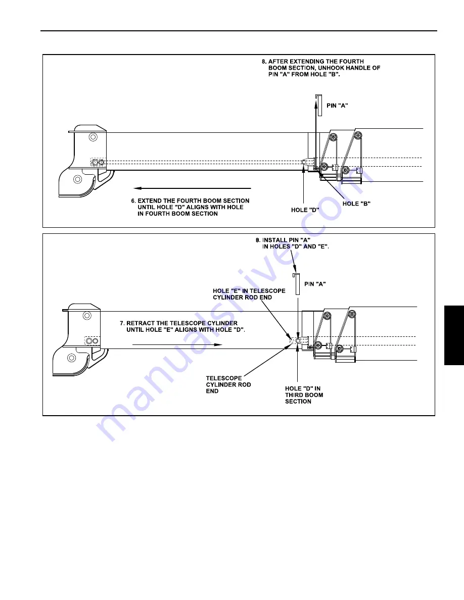
Page 82: ...g procedure to extend and retract the fourth boom section Extending the Fourth Boom Section 1 Extend the outriggers 2 Lower the boom to its horizontal position 3 Completely retract the boom 4 On the left side of the boom remove pin A Figure 5 3 from hole D by first removing the snapper pin retaining pin A and then the pin 5 Hook the handle of pin A in hole B 6 Fully extend the fourth boom section ...
Page 83: ...GROVE Published 10 21 2011 Control 055 03 5 3 5540F YB5515 OPERATOR S MANUAL ATTACHMENTS 5 FIGURE 5 4 a1851 FIGURE 5 5 a1854 R e f e r e n c e O n l y ...
Page 84: ... pin A from holes D and E at the rear of the fourth boom section and the bracket on the third boom section 5 Hook the handle of pin A into hole B 6 Fully extend the telescope cylinder by actuating the telescope lever in the cab Figure 5 7 7 Install pin A into holes C and F 8 Completely retract the fourth boom section Figure 5 8 9 Remove pin A from hole C 10 Install pin A into holes D and E Install...
Page 85: ... sheave bracket into an upright position Install and secure the pin removed at location No 11 into location No 12 7 Remove the hoist block from the hoist wire rope 8 Remove the wire rope from the boom head sheaves 9 Using the hoist control release more wire rope from the hoist drum and install the wire rope over deflector sheave at the base of the boom extension 10 Remove the two pins A and B Figu...
Page 86: ... No 5 Install and secure the pin 9 Remove the pin at location No 4 and swing the boom into position so the pin removed at location No 10 can be installed at location No 1 Install and secure the pin 10 Install and secure the pins removed from locations No 4 and 9 back into those positions on the boom extension to inhibit loosing the pins 11 Remove the pin at location No 12 Swing the deflector sheav...
Page 87: ...he transmitter from the boom head by removing the transmitter mounting hardware bolts lockwashers and flat washers 3 Follow instructions at the beginning of this section to remove the hoist block 4 Using the hardware removed when removing the load indicator transmitter install the transmitter onto the downhaul weight See Figure 5 11 5 Remove the rope guide pin indicated in Figure 5 11 from the dow...
Page 88: ...hardware 7 Install the hoist block using instructions in this section Install the load pin 8 Connect the transmitter wire Figure 5 10 to the load pin wire INSTALLING CABLE ON THE HOIST NOTE The cable should preferably be straightened before installation on the hoist drum Install cable on the hoist drum in accordance with the following procedure 1 Position the cable over the boom nose sheave and ro...
Page 89: ...che ball or hook block striking the ground etc Sketches A through F Figure 5 14 illustrate various ANSI approved methods for treating the dead ends of wire ropes which exit a wedge socket assembly While use of the loop back method is acceptable care must be exercised to avoid the loop becoming entangled with tree branches and other components during crane transport and with the anti two block syst...
Page 90: ... 1 8 3 18 4 5 6 3 16 4 76 7 5 10 1 4 6 35 15 20 5 16 7 94 30 40 3 8 13 28 45 60 7 16 11 11 65 90 1 2 12 70 65 90 9 16 14 29 95 130 5 8 15 88 95 130 3 4 19 05 130 175 7 8 22 23 225 300 1 25 40 225 300 1 1 8 28 58 225 300 1 1 4 31 75 360 490 1 3 8 38 68 360 490 1 1 2 38 10 360 490 FIGURE 5 14 Wedge Socket Specialty Clip Specialty Wedge R e f e r e n c e O n l y ...
Page 91: ... the rope through the second sheave in the hoist block NOTE It may be easier to place the wire rope over the sheaves if you remove the hair cotter pins and wire rope retaining pins from the boom head and hoist block Install pins after the wire rope is installed Connect the loose end of the wire rope to the ear on the crane side of the boom head with a socket and wedge See instructions in this sect...
Page 92: ...ATTACHMENTS 5540F YB5515 OPERATOR S MANUAL 5 12 Published 10 21 2011 Control 055 03 THIS PAGE BLANK R e f e r e n c e O n l y ...
Page 93: ...tion as long as possible Adjust the maintenance schedule to your operation according to the type of work size of loads temperature conditions and frequency of equipment use The intervals in the Maintenance Schedule are for average operating conditions and must be understood as the MINIMUM maintenance necessary for the machine Decrease these intervals if the machine is operated in conditions that a...
Page 94: ...evel is low Hydraulic Tank Check oil level Fill if level is low Drive Axles Check axle housing lubricant level and wheel hub lubricant level Fill if levels are low Hoist Gearbox Check oil level Fill if level is low Tires Check for correct air pressure Wire rope cable clamps and connections Check for loose or missing parts Anti Double Blocking System Check that the system is working properly Contro...
Page 95: ... indicates the total hours the crane has been running In addition to the following scheduled maintenance perform the scheduled maintenance suggested in the engine manual furnished with the crane When performing maintenance do the required maintenance interval as well as all previous interval maintenance For example when performing the 250 hour monthly maintenance interval perform all the tasks req...
Page 96: ...vel x Check fuel level x Check tire pressure x Check tire pressure x Drain water from engine fuel filter x Check air cleaner restriction indicator x Check hydraulic oil level x Inspect wire rope and sheaves x Apply grease to all lubrication fittings x Lubricate the boom slides x Lubricate the boom chains x Clean air cleaner duct cup x Lubricate parking brake fitting x Inspect engine fan belts x Ch...
Page 97: ...ment x Clean and adjust spark plug gap gasoline engine x Check swing gear to pinion backlash x Replace the transmission oil and filter x Replace the axle wheel hub lubricant x Replace the axle housing lubricant x Replace the hoist gearbox lubricant x Replace the hydraulic oil x Replace the hydraulic oil filter x Replace the L P G inline filter x Replace the in line fuel filters gasoline x Replace ...
Page 98: ...ure 6 2 2 Boom Head Sheaves and Pivot see Figure 6 3 2 Lift Cylinder Pivots see Figure 6 5 2 Drive Train Location QTY Steering Knuckles front axle see Figure 6 6 4 Steering Knuckles rear axle see Figure 6 7 4 Steering Link front axle see Figure 6 8 2 Steering Link rear axle see Figure 6 9 2 Steering Cylinder Pivot Ends front axle see Figure 6 10 2 Steering Cylinder Pivot Ends rear axle see Figure ...
Page 99: ...d On Inside Surface or Bearing Ring FIGURE 6 1 p1663 Boom Pivot Lubrication Points FIGURE 6 2 p1622 Boom Head Sheaves and Pivot Lube Points FIGURE 6 3 p1639 Lift Cylinder Pivots Lube Points Base End FIGURE 6 4 p1664 Lift Cylinder Pivots Lube Point Rod End FIGURE 6 5 p0417 Steering Knuckle Lube Points Front Axle FIGURE 6 6 R e f e r e n c e O n l y ...
Page 100: ... Lube Points Rear Axle FIGURE 6 7 p0419 Steering Link Lube Points Front Axle FIGURE 6 8 p0422 Steering Link Lube Points Rear Axle FIGURE 6 9 p0418 Steering Cylinder Pivot Ends Lube Points Front Axle FIGURE 6 10 p0420 Steering Cylinder Pivots Ends Lube Points Rear Axle FIGURE 6 11 R e f e r e n c e O n l y ...
Page 101: ... Lower the hoist block and the alarm will stop f there is a malfunction in the system DO NOT operate the crane Have the malfunction corrected Inspect the Wire Rope Each day before beginning operation visually inspect the wire rope for damage See 50 Hours of Operation Weekly on page 6 14 for examples of damage that can be visually inspected for If any damage is found do not operate the crane The wi...
Page 102: ...oking materials away from the crane and fuel during refueling or fuel system servicing Know the location of the fire extinguishers on the job site and how to use them Maintain control of the hose nozzle when filling the fuel tank Do not allow fuel to spill Clean up spilled fuel immediately Dispose of clean up materials properly DO NOT fill the fuel tank to capacity Allow room for fuel expansion Ti...
Page 103: ... Check that the overflow bottle Figure 6 17 is at least half full If coolant is low fill the overflow bottle half way with a 50 50 mixture of glycol antifreeze and water Do not add only water as this could cause rust to form in the radiator and engine 3 If the bottle is empty BE SURE THE ENGINE IS COOL to below 120 F 50 C then slowly loosen the radiator cap to the first stop Allow all pressure to ...
Page 104: ...tion can do Ridges of dirt on the gasket sealing surface can drop on the clean filter side when the gasket is released Remove the Element NOTE Service the air cleaner only with the engine shut down Dirt and debris can enter the engine and cause damage if the engine is operated with the air cleaner element removed 1 Remove the housing cover 2 Remove the wing nut securing the air cleaner element to ...
Page 105: ...imum pressure at the nozzle 2 Direct the air inside the element and then move the nozzle up and down while rotating the element Install the Element 1 Install the safety element over the stud in the housing and slide it all the way in 2 Install and tighten the wing nut Hand tighten it only Install the element over the stud in the housing and slide it all the way in 3 Make sure the gasket is seating...
Page 106: ... by a person who has learned through special training or practical experience what to look for and who knows how to judge the importance of any abnormal conditions they may discover It is the inspector s responsibility to obtain and follow proper inspection criteria for each application inspected If you are not familiar with wire rope inspection information on how to inspect wire rope sheaves and ...
Page 107: ...lts 5 On four section booms only align the boom access holes Figure 6 23 to gain access to the telescope cylinder rod end slide pad 6 Apply bronze anti seize or equivalent to the inner boom surface in front of and behind the slide block Only use a small amount of lubricant for best results Extend and retract the booms to distribute the lubricant along the slide path Evidence of heat damage from an...
Page 108: ...MAINTENANCE 5540F YB5515 OPERATOR S MANUAL 6 16 Published 10 21 2011 Control 055 03 a1876 FIGURE 6 23 R e f e r e n c e O n l y ...
Page 109: ...ation and increased wear A belt that is too tight produces wear on the belt and the bearings of the pulleys it travels around Check ribbed belts for intersecting cracks Cracks across the belt are acceptable Cracks along the length of a ribbed belt are not acceptable Ribbed belts with cracks along their length should be replaced See Figure 6 24 Any ribbed belt showing signs of wear or that has mate...
Page 110: ...tings and worn exterior Do not use your hands to check for hydraulic leaks Hydraulic oil under pressure can cause serious injury or possible death Use a piece of cardboard or other material as a deflector to detect leaks Replace any problem hose before beginning work Clean Battery and Cables 1 Remove the battery compartment cover 1100263 p1652 Battery Location FIGURE 6 25 R e f e r e n c e O n l y...
Page 111: ... To inhibit personal injury from compressed air always wear safety glasses when using compressed air for cleaning 3 After cleaning the wire rope apply a good grade of wire rope lubricant to the entire length of the wire rope Or apply a light weight oil that has been preheated to a temperature between 60 and 100 F 18 to 36 C Use a brush or cloth to apply the oil NOTE Be sure the lubricant enters th...
Page 112: ...n engine oil to the gasket of the new oil filter Turn the filter clockwise to tighten it until the gasket makes contact Then tighten the filter 1 2 to 3 4 turn to get correct seal 8 Fill the engine crankcase with clean recommended lubricating oil 9 Operate the engine at idle and inspect for leaks at the filter and drain plug Torque Critical Bolts NOTE Maintain correct torque on all bolts Failure t...
Page 113: ...028 inches 0 71 mm thick or less Check the surface condition of the brake disc Replace the disc if badly warped pitted or out of tolerance Replace Fuel Filter Diesel Engine See the engine operator s manual furnished with the crane and follow the replacement procedures NOTE If the filter is not filled with fuel prior to installation the engine will not start due to air in the fuel system The fuel s...
Page 114: ... 0 030 inch 0 76 mm feeler gauge If not correct reset the gap Add Rust Inhibitor to Engine Cooling System For maximum protection of the engine cooling system add a corrosive inhibitor to the radiator When the engine is cold remove the radiator cap and pour the inhibitor in the radiator reservoir following manufacturer s instructions Lubricate the Outrigger Slides 1 Lower the outriggers 2 Clean the...
Page 115: ...re 6 34 and Figure 6 35 and remove the plug 2 Check the lubricant level which should be even with the bottom of the fill check hole 3 If necessary add Mobil Fluid 424 to fill the housings until oil is level with the bottom of the fill check hole Check Wheel Hub Lubricant Level 1 Using the outriggers raise the tires slightly off of the ground 2 Place the transmission in neutral and release the park...
Page 116: ...ed with this crane Replace the Transmission Oil and Filter 1 Engage the parking brake and shut off the engine Remove the ignition key NOTE It is necessary to climb under the crane to drain the transmission oil Be sure engine is shut off the ignition key is removed parking brake is engaged and chock blocks are in place before climbing under the crane When the strainer is loosened removed oil will g...
Page 117: ...fill the transmission filter torque converter and hoses 11 Stop the engine wait approximately one minute and then check oil level If low add oil to the upper mark on the transmission dipstick DO NOT OVERFILL Replace the Axle Housing Lubricant NOTE It is necessary to climb under the crane to drain the axle housing lube Be sure engine is shut off the ignition key is removed and chock blocks are in p...
Page 118: ...el hub Figure 6 45 4 Clean around the drain plug and then remove it Drain the wheel hub oil into a suitable container 5 Turn the wheel hub until the drain hole is horizontal Figure 6 46 6 Fill the wheel hub with the recommended lubricant through the fill hole until the oil reaches the bottom of the hole 7 Install the plug 8 Repeat the above procedure for the other three wheel hubs p0429 Axle Housi...
Page 119: ... even with the bottom of the fill hole Fill with SAE 90 EP gear lube 9 Install the fill check plug Replace the Hydraulic Oil NOTE ISO International Standards Organization 46 68 Hydraulic Oil Mobil Fluid 424 is recommend for year round use in the hydraulic system In very cold temperatures SAE 5W or SAE 5W 20 oils can be used if the viscosity of the oil will not be less than 60 SUS Saybolt Universal...
Page 120: ...g under the crane 2 Locate the hydraulic oil filter under the machine Figure 6 50 3 Remove the filter a Using a filter wrench turn the filter counterclockwise to loosen and remove the filter Properly discard the removed filter b Clean the mounting surface on the filter head for the filter 4 Install the filter a Apply a small amount of clean hydraulic oil to the gasket of the new hydraulic filter I...
Page 121: ...uel Filter Dual Fuel Engine NOTE It is necessary to climb under the crane to change the fuel filter Be sure engine is shut off the ignition key is removed and chock blocks are in place before climbing under the crane 1 Engage the parking brake and shut off the engine 2 Disconnect the two clamps and remove the filter 3 Install a new filter between the hoses and secure it in place with the two clamp...
Page 122: ...f less than 10 volts with the engine at low idle indicates a low battery charge A reading of less than 14 volts with the engine speed above low idle indicates a problem in the charging system The system should be checked out by an qualified service technician Charging the Battery Under normal conditions the engine s alternator will have no problem keeping a charge on the batteries The only conditi...
Page 123: ...ediment dirt water and other foreign materials in the fuel Many engine problems are caused by dirty fuel and long storage periods Keep fuel in an outside location Use a shelter to keep the fuel as cool as possible The water from condensation must be removed at regular intervals from the storage tank Fuse Replacement Ten fuses are located on a fuse block in the instrument panel Figure 6 52 WARNING ...
Page 124: ...MAINTENANCE 5540F YB5515 OPERATOR S MANUAL 6 32 Published 10 21 2011 Control 055 03 p1645 Fuse Cover Location FIGURE 6 52 R e f e r e n c e O n l y ...
Page 125: ...CTION 7 ADJUSTMENTS SECTION CONTENTS All adjustments must be performed by a qualified mechanic 7 1 Refer to the Service Manual for the proper procedures 7 1 ALL ADJUSTMENTS MUST BE PERFORMED BY A QUALIFIED MECHANIC Refer to the Service Manual for the proper procedures R e f e r e n c e O n l y ...
Page 126: ...ADJUSTMENTS 5540F YB5515 OPERATOR S MANUAL 7 2 Published 10 21 2011 Control 055 03 THIS PAGE BLANK R e f e r e n c e O n l y ...
Page 127: ...qts 4 3 liters 5 5 qts 5 2 liters See Fuel Types Engine crankcase diesel engine Without filter change With filter change 10 0 qts 9 5 liters 11 5 qts 10 9 liters See Fuel Types Fuel tank 40 gal 151 4 liters See Fuel Types Cooling system 23 qts 21 9 liters 50 50 Mixture of Glycol Anti freeze water Hydraulic tank 40 gal 151 4 liters Mobil Fluid 424 or equivalent ISO 46 68 Very Cold Temperatures SAE ...
Page 128: ... single grade lubricating oils is not recommended except for synthetic oils used in Arctic conditions Viscosity Grades Arctic Operation NOTE SAE 5W viscosity grade synthetic oil may be used when operating the engine in ambient temperatures below 10 F 23 C provided they meet the minimum viscosity at 212 F 100 C When there is no provision to keep the engine warm when operating in ambient temperature...
Page 129: ...mmended for industrial engines FUEL TYPES Diesel Fuel The Cummins Diesel Engine operates most efficiently with No 2 diesel fuel in temperatures above 32 F 0 C When operating in temperatures below 32 F 0 C use No 1 diesel fuel or a blend of No 1 and No 2 diesel fuels most commonly known as Winterized No 2 diesel Use ASTM No 2 diesel fuel with a minimum Cetane number of 40 No 2 diesel fuel gives the...
Page 130: ... 700 rpm Maximum engine speed 2600 rpm Tires Size 385 65R22 5 Type Radial Air pressure 120 psi 828 kPa Wheel nut torque 500 lb ft 680 Nm Electrical System Rating 12 VDC negative ground Number and type of batteries Standard One maintenance free With optional cold weather start Two Battery rating 90 amp hr Alternator 63 amps Boom Reach from center line of rotation 3 Section Boom 41 0 12 50 m Relief ...
Page 131: ...n filter in tank Weight Crane 26 300 lb 11 930 kg Travel Speeds Two Wheel Steer 1st gear 3 7 mph 6 0 km hr 2nd gear 75 8 mph 9 3 km hr 3rd gear 11 8 mph 19 0 km hr 4th gear 14 5 mph 23 3 km hr Operating Dimensions Two Wheel Steer Outside turning radius center line outside tires 21 6 6 55 m Minimum aisle space for 90 turn center line inside tires 12 4 3 76 m Four Wheel Steer Outside turning radius ...
Page 132: ...SPECIFICATIONS 5540F YB5515 OPERATOR S MANUAL 8 6 Published 10 21 2011 Control 055 03 DIMENSIONS 1710362 FIGURE 8 1 R e f e r e n c e O n l y ...
Page 133: ...e On The Hoist 5 8 Introduction 6 1 Lubricants And Capacities 8 1 Lubricants 6 2 Machine Operation 3 13 Maintenance Records 6 2 Miscellaneous Maintenance 6 30 Nomenclature 1 3 Operating Practices 3 30 Operating the Outrigger Controls 3 20 Operational Aids 2 3 Operator s Cab 3 11 Operator s Information 2 2 Operator s Qualifications 2 3 Overload Inspection 2 24 Parking and Securing 2 22 Personnel Ha...
Page 134: ...THIS PAGE BLANK R e f e r e n c e O n l y ...