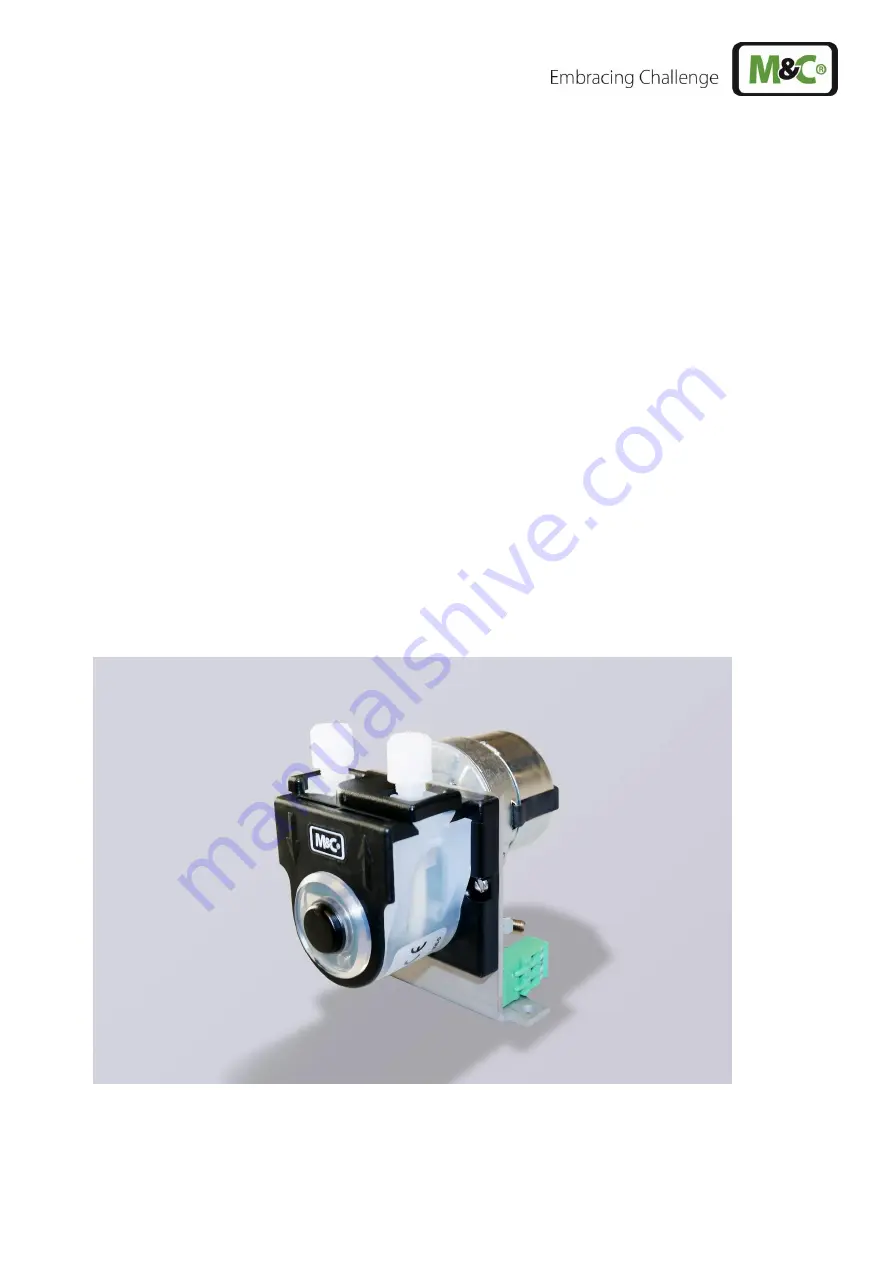
Peristaltic Pump Series SR
®
SR25.2, SR25.2-G, SR25.2-W SR25.3, SR25.3-G, SR25.3-W SR25.6, SR25.6-G, SR25.6-W
Instruction Manual Version 1.01.01
Page 1: ...Peristaltic Pump Series SR SR25 2 SR25 2 G SR25 2 W SR25 3 SR25 3 G SR25 3 W SR25 6 SR25 6 G SR25 6 W Instruction Manual Version 1 01 01 ...
Page 2: ...e don t hesitate to contact M C or your M C authorized distributor You will find all the addresses in the appendix of this manual For additional information about our products and our company please go to M C s website www mc techgroup com There you will find the data sheets and manuals of all our products in German and English This Operating Manual does not claim completeness and may be subject t...
Page 3: ... Maintenance 17 15 1 Changing the pump tubing 18 15 2 Changing contact pulleys and springs 19 15 2 1 Reassembly of the driver 20 15 3 Cleaning the pump head 21 16 Repair information 21 17 Spare parts list 22 18 Appendix 22 List of illustrations Figure 1 Dimensions SR25 X 10 Figure 2 Drilling pattern for SR25 X 11 Figure 3 Dimensions SR25 X W 11 Figure 4 Dimensions SR25 X G 12 Figure 5 SR25 2 Mount...
Page 4: ...s closely Read this manual carefully before commissioning and operating the device If you have any questions regarding the product or the application please don t hesitate to contact M C or your M C authorized distributor 2 DECLARATION OF CONFORMITY CE Certification The product described in this operating manual complies with the following EU directives RoHS Directive The requirements of the RoHS2...
Page 5: ...pening the device for access Make sure that all extern power supplies are disconnected Operate the device only in the permitted temperature and pressure ranges For details please refer to the technical data sheet or manual Install the device only in protected areas sheltered from sun rain and moisture The product should not be exposure to the elements Installation maintenance inspections and any r...
Page 6: ...Attention indicates that an unintended result or situation can occur if the corresponding information is not taken into account Note Note indicates important information relating to the product or highlights parts of the documentation for special attention Qualified personnel Qualified personnel are experts who are familiar with the installation mounting commissioning and operation of these types ...
Page 7: ...temperatures requires wearing protective gloves Wear safety glasses Protect your eyes while working with chemicals or sharpe objects Wear safety glasses to avoid getting something in your eyes Wear protective clothes Working with chemicals sharpe objects or extremly high temperatures requires wearing protective clothes ...
Page 8: ...rminal 1 5 mm2 Terminal 1 5 mm2 1 x M20 x 1 5 Terminal 1 5 mm2 Dimensions HxWxD 84 x 64 x 52 mm plus 40 mm for the motor 3 31 x 2 50 x 2 04 plus 1 56 for the motor 126 x 105 x 108 mm 4 98 x 4 13 x 4 26 107 x 80 x 94 mm 4 21 x 3 15 x 3 71 0 4 kg 0 88 lb 0 6 kg 1 32 lb 0 5 kg 1 10 lb Suction max 200 mbar abs Pressure max 2200 mbar abs Sample temperature 0 to 60 C 32 to 140 F Ambient temperature 0 to...
Page 9: ...ant occupational safety regulations during operation Warning Disconnect power supply before opening the device for access Make sure that all external power supplies are disconnected Aggressive condensate possible Media residues in tubing Chemical burns caused by aggressive media possible Wear protective gloves and protective glasses Wear proper protective clothing Peristaltic pump is under pressur...
Page 10: ...ctor DN 4 6 also allows connecting PTFE tubing The peristaltic pump SR25 X X can be equipped with a power supply of 230 V 50 Hz or 115 V 60 Hz Danger Type SR25 X has open electrical wiring Risk of death due to electric shock The unused wires must be safely insulated preferably to a third free terminal The following installation options are available Type SR25 X to integrate into a front plate Type...
Page 11: ... com SR25 X X 1 01 01 11 Figure 2 Drilling pattern for SR25 X Metric dimensions mm are rounded Inch dimensions are for reference only In case of doubt or conflict metric units take priority Figure 3 Dimensions SR25 X W ...
Page 12: ...p is a complete pre installed unit Please remove the peristaltic pump carefully from the packaging Check the scope of the delivery specified on the delivery note Please make sure that you have received all items stated on the delivery note Please check the unit for any transport damages after receipt and report any complaints to the transport company immediately Note The peristaltic pump must be s...
Page 13: ...entilated to prevent any accumulation of heat For outdoor installation the pump must be installed in a housing protected from frost in the winter and sufficiently ventilated in summer Exposure to direct sunlight must be avoided Danger It is therefore essential to provide protection for persons against contact with alive parts e g electrical connections motor windings and moving parts e g fan Prote...
Page 14: ...e connections for sample gas inlet and outlet the connections are marked accordingly Check for tightness of all sample lines after connecting Connect the tubing to the regular tubing connectors as follows Remove the union nut from the sealing ring couplings by turning it anti clockwise The nut should be removed from the thread with great care to ensure that the loose sealing ring inside the nut is...
Page 15: ...glasses Wear proper protective clothing 12 2ELECTRICAL CONNECTIONS Connect the cables for the power supply as follows Figure 6 Supply voltage connection for SR25 X W and SR25 X G The supply voltage of the SR25 X peristaltic pump must be connected as follows Connection at 230 V blue wire red wire Connection at 115 V white wire blue wire Danger Open electrical wiring Risk of death due to electric sh...
Page 16: ...t over current protection EN 60335 1 A device to separate the motor from the power supply needs to be provided as part of the electrical installation EN 60335 1 The pump must be installed in such a way that contact with alive parts connections possibly windings is impossible 13 START UP Specific safety instructions for media being handled must be observed Before pumping a medium the compatibility ...
Page 17: ... that all external power supplies are disconnected Aggressive condensate possible Media residues in tubing Chemical burns caused by aggressive media possible Wear protective gloves and protective glasses Wear proper protective clothing Peristaltic pump is under pressure Do not open housing A peristaltic pump might be part of a system which is under pressure Check pressure before opening peristalti...
Page 18: ...e connectors Press the two contact pulleys and check whether the spring pressure is still sufficient if not the contact springs have to be changed see chapter 15 2 Put the new tubing set with the tube connectors into the guides of the conveying belt Note Only the usage of the original tubing set guarantees a proper functionality Never lubricate the tube Before mounting the pump check all parts for...
Page 19: ...f the shaft bore Figure 9 Disassembly of pump head and driver Remove the pump head from the motor shaft Now the driver can be removed from the pump head and is ready for maintenance The removal of the springs 4 pcs away from the driver is easily possible without the aid of any tools For this take spring out of the groove near to the shaft bore Dismount roller axes and change contact pulleys Take c...
Page 20: ...ngs and will replace without any problems the initial springs The replacement springs guarantee full functionality when all four springs are replaced Make sure that contact pulleys move easily on the axis After remounting the axis with contact pulley into the driver the spring has to be mounted as shown as in Figure 10 Please pay attention to the alignment of the dent 15 2 1 REASSEMBLY OF THE DRIV...
Page 21: ...d synthetic rubber parts Use oil free compressed air to clean the parts if available Aggressive condensate possible Media residues in tubing Chemical burns caused by aggressive media possible Wear protective gloves and protective glasses Wear proper protective clothing 16 REPAIR INFORMATION Note When sending the peristaltic pump to M C customer service for repair please indicate the type of medium...
Page 22: ... C 1 2 4 90 P 1006 Tubing set with PVDF tube nipples 6mm C 1 2 4 90 P 1020 Roll carier driver SR25 complete S 1 1 90 P 1010 1 set 4 pcs contact springs SR25 for driver R 1 2 2 90 P 1015 1 set 4 pcs reinforced contact springs SR25 for driver Masterflex tubing R 1 2 2 90 P 1045 Pressure roll contact pulley SR25 PVDF for driver S 2 4 4 90 P 1050 Conveying belt S 1 2 90 P 1025 Locking bolt S S bolt S ...
Page 23: ...www mc techgroup com SR25 X X 1 01 01 23 Figure 11 Spare parts Drawing No 2435 1 07 0 ...