Ref.: WB-VL-SM Ver.1 3.doc
3
Proper Earthing must be provided. Also ensure that live phase is on the
correct side of the socket as per the country requirement. It is strongly
recommended to use a CVT (1KVA capacity for LCV models and 3KVA
capacity for HCV models).
Neutral to Line Volt should be 230VAC ±10% (for LCV with 230V operation)
Neutral to Line Volt should be 110VAC ±10% (for LCV with 110V operation)
Line to Line Volt should be 415VAC ±5% (for HCV with 400V operation)
Line to Line Volt should be 220VAC ±5% (for HCV with 220V operation)
Neutral to Earth should be less than 3V AC (NA for without Neutral in HCV)
Line to Line Volt should be 220VAC ±5% (for HCV single phase model with
220V / 60HZ operation)
Neutral to Line Volt should be 230VAC ±10% (for HCV Single phase model
with 230V/ 50Hz operation)
2.2.3. SPACE REQUIREMENTS
1.
The floor should be properly leveled beneath the Balancer and should
be free of heavy equipment vibrations.
2.
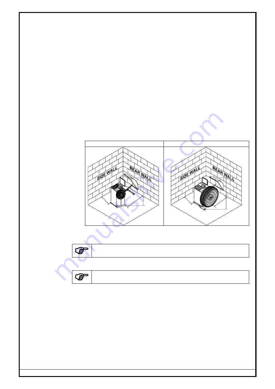
The clearances from side walls and roof should be adequate so that the
Wheel guard can be opened completely and the mounting / removal of
wheels can be done easily as shown below.
LCV model
HCV model
600
700
1720
600
800
1800
Fig. 1
3.
The equipment should be anchored to the floor by using the Anchor
bolts supplied along with the equipment.
Proof of safe floor load capacity is the owner's responsibility
2.2.4. ACCESSORIES & TOOLS REQUIREMENTS
Provision of handling means such as Forklifts etc. is the owner's
responsibility
The following accessories and tools are required for the proper installation of
the equipment:
1.
Screw drivers, Spanner set and Allen key set
2.
Measurement Tape
– 5 metre
3.
Chalk liner/ Marker pen - for marking
4.
Strip cutter - to Open Carton Banding
5.
knife
– for opening Cartons
6.
Plastic cable Ties
– for proper routing of cables
7.
Multi-meter
– for verifying supply voltage
8.
Nylon Hammer
9.
Hammer Drill and 12mm Drill bit
10.
‘U’ type Shims (required QTY) - 0.5mmT, 1.0mmT, 1.5mmT & 2.0mmT
2.3.
2.3.
2.3.
2.3.
Summary of Contents for LX WB-VL-65 DSP
Page 48: ...Ref WB VL SM Ver 1 3 doc 45 7 DIAGRAMS 7 1 BLOCK DIAGRAM 7 1 1 LCV MODELS Fig 99...
Page 49: ...Ref WB VL SM Ver 1 3 doc 46 7 1 2 HCV MODEL THREE PHASE OPERATION Fig 100...
Page 50: ...Ref WB VL SM Ver 1 3 doc 47 SINGLE PHASE OPERATION Fig 101...
Page 51: ...Ref WB VL SM Ver 1 3 doc 48 7 2 WIRING DIAGRAM 7 2 1 LCV MODELS Fig 102 1 of 3...
Page 52: ...Ref WB VL SM Ver 1 3 doc 49 Fig 102 2 of 3...
Page 53: ...Ref WB VL SM Ver 1 3 doc 50 Fig 102 3 of 3...
Page 54: ...Ref WB VL SM Ver 1 3 doc 51 7 2 2 HCV MODEL THREE PHASE OPERATION Fig 103 1 of 3...
Page 55: ...Ref WB VL SM Ver 1 3 doc 52 Fig 103 2 of 3...
Page 56: ...Ref WB VL SM Ver 1 3 doc 53 SINGLE PHASE OPERATION Fig 103 3 of 3...


