


Functional safety
24
Read this manual carefully before starting any work!
This is particularly applicable to the chapter “General Safety Instructions”
and the respective safety instructions in the chapters.
3.2.2
“Class” Application
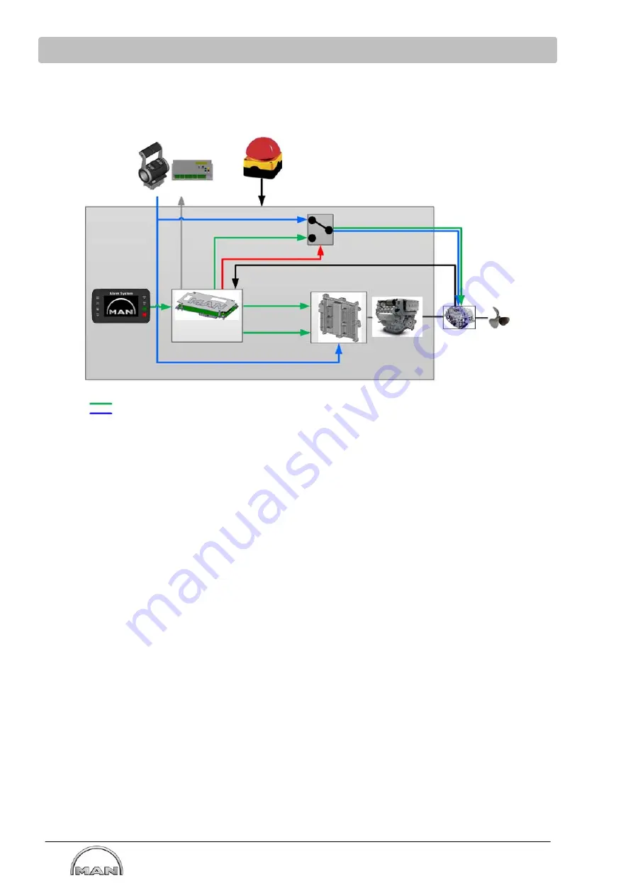
Local operator´s platform
Signal source:
Connection CAN:
- Display
- Start/stop
- Speed adjustment
- Gearbox setting
specification
Drive lever control
Local operatorʼs
platform
Drive lever control unit
System off
Gearbox control (Fwd / Neutr. / Rvs.)
Gearbox control (Fwd / Neutr. / Rvs.)
Gearbox shifting
Feedback of current
engine speed
Feedback of current gearbox position
Engine CU
Speed setpoint
(via engine CAN)
Engine
Bolt
Monitoring Control
System (MCS)
Start/Stop
(via engine CAN)
Gearbox
Fwd / Neutr. / Rvs.
Speed setpoint (4…20 mA)
Start / Stop / start release (hardwired)
The engine control unit receives the engine start/stop requirements as well as the speed setpoint either
from the MCS control unit via CAN or reads them in directly via analog or digital inputs.
The switchover between the two setpoint paths is performed in the engine control unit. The trigger for this
is provided by the MCS control unit via CAN.
In order to change the direction of rotation of the shipʼs propeller, a
reverse gearbox
is installed, which is
controlled by the MCS control unit or the drive lever control via the E-Box.
-
The combustion engine is coupled directly to the shipʼs propeller via a closed drive train. A torque is
transmitted to the gearbox. The gearbox and the shipʼs propeller are not part of the system.
-
The combustion engine is controlled and monitored by the engine’s electronic control unit (ECU).
-
The target speed is specified to the engine control unit by the Monitoring Control System (MCS) or
directly via a 4...20 mA signal from the drive lever control unit.
As a rule, the 4...20 mA input is used for the speed setpoint. All other sources are only used in
exceptional cases, e.g. during maintenance work, failure of the main path, or special applications
-
The MCS provides the signal for controlling a reverse gear. The system is able process gear signals
from several sources and generate the setting:
1. Drive lever control unit
2. Local control unit
-
The engine start and stop requests to the engine control unit are specified either via the MCS (from the
local operatorʼs platform) via CAN or directly (hardwired) from the drive lever control unit.
Summary of Contents for iSea
Page 1: ......
Page 2: ......
Page 163: ...Wiring diagram Marine shipyard classified...
Page 164: ......
Page 165: ...Wiring diagram Marine shipyard non classified...
Page 166: ......
Page 170: ......
Page 171: ......
Page 172: ......