


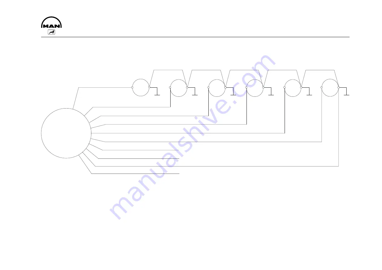
Cable harness for the output signals from the control unit
for E 0826 E engines
+
–
+
+
+
1
–
–
–
–
–
+
+
2
3
4
5
6
cylinder
A
E
C
F
B
D
G
H
I
J
7
1, 2, 3, 4, 5, 6 Ignition coils of the respective cylinders
D brown (cylinder 6)
(the 1
st
cylinder is located at the non-flywheel end)
E blue (cylinder 2)
F orange (cylinder 4)
7 Plug
G white / green (not used)
A red (cylinder 1)
H white / orange (not used)
B yellow (cylinder 5)
I white (minus)
C green (cylinder 3)
J grey (rev counter)
Summary of Contents for E 0824 E 301
Page 1: ......
Page 2: ......
Page 14: ...Commissioning and operation 12 Engine views E 0824 E 301 302 1 2 3 4 5 6 7 8 9 10 11 12...
Page 16: ...Commissioning and operation 14 Engine views E 0826 E 301 302 1 2 3 4 5 6 7 8 9 10 11 12...
Page 35: ...Notes 33...
Page 41: ...39 Circuit diagrams...
Page 45: ...Notes 43...
Page 47: ......
Page 48: ......